Edge seals for, and processes for assembly of, electro-optic displays

a technology of electrooptic display and process, applied in nanotechnology, thin material processing, instruments, etc., can solve the problem that the sealing layer of ceramics is susceptible to brittle fractur

Active Publication Date: 2006-12-28
E INK CORPORATION
View PDF2 Cites 188 Cited by
  • Summary
  • Abstract
  • Description
  • Claims
  • Application Information

AI Technical Summary

Benefits of technology

[0041] For convenience, this type of electro-optic display may hereinafter be called a “sealed electro-optic display” of the present invention. Also, for convenience, the layer of metal or ceramic used in the display may hereinafter be called the “sealing layer”. This sealing layer is preferably vapor deposited. In general, metal sealing layers are preferred over ceramic layers in flexible displays, since ceramic sealing layers may be...

Problems solved by technology

In general, metal sealing layers are preferred over ceramic layers in flexi...

Method used


Image

  • Edge seals for, and processes for assembly of, electro-optic displays
  • Edge seals for, and processes for assembly of, electro-optic displays
  • Edge seals for, and processes for assembly of, electro-optic displays

Examples


Embodiment Construction

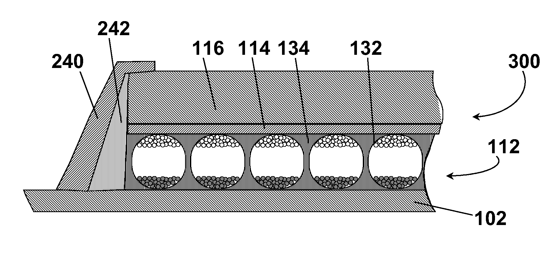
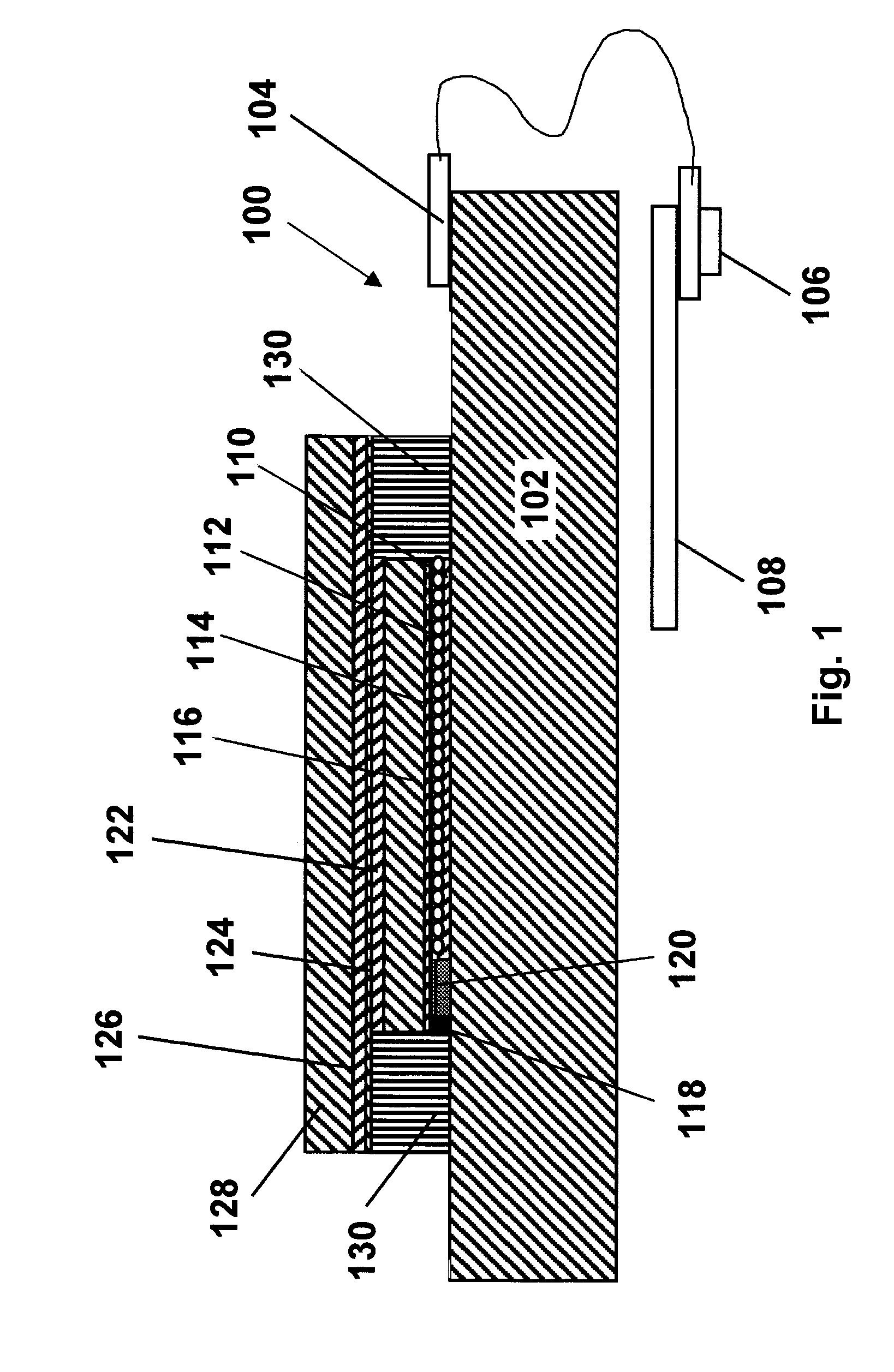
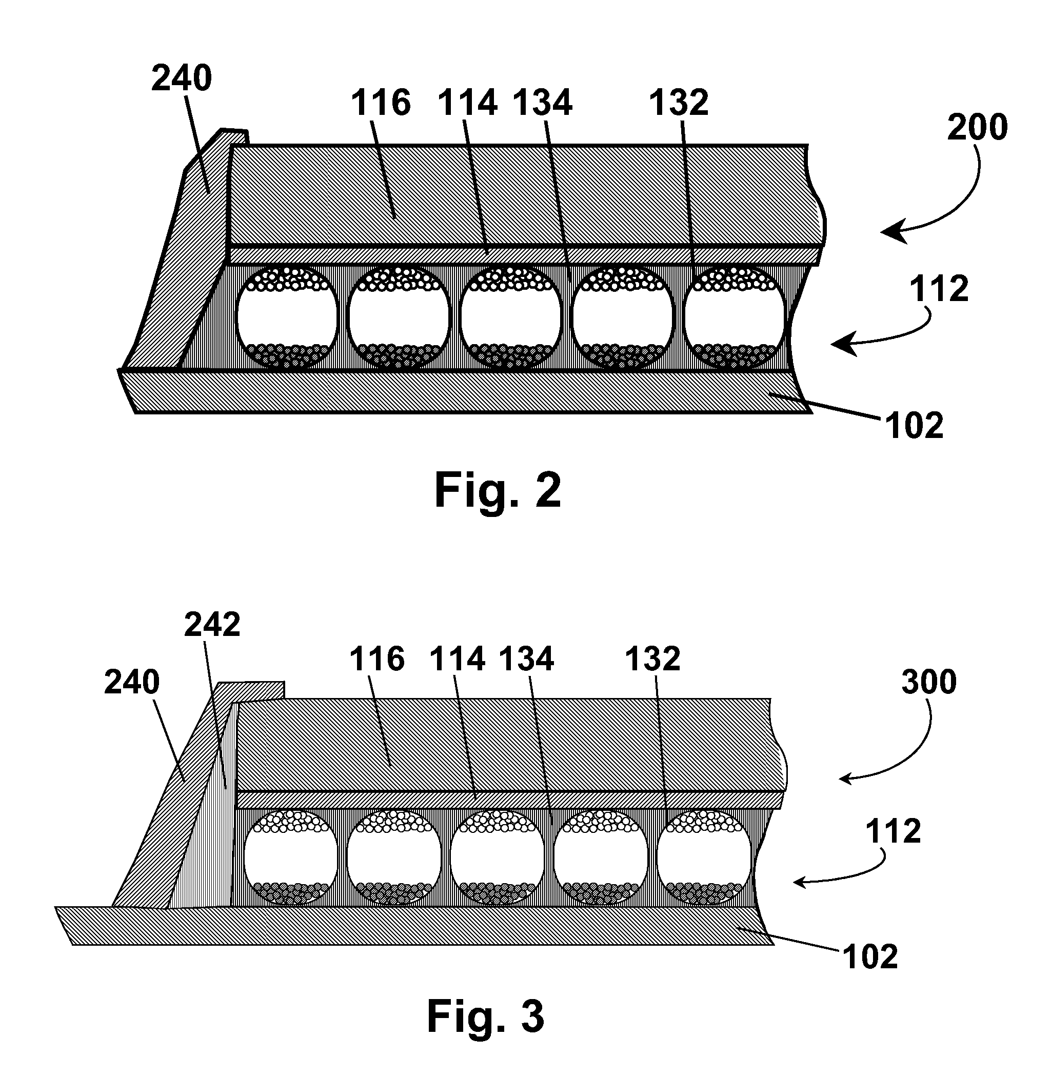
[0061] As indicated above, the present invention has several different aspects, which will be described separately below. However, it should be noted that a single electro-optic display may make use of more than one aspect of the present invention; for example, an electro-optic display could have its electro-optic medium coated by a coating process of the present invention and be edge sealed using an edge seal of the present invention. Similarly, one aspect of the present invention relates to coating of electro-optic media on to substrates to form an electro-optic medium / substrate sub-assembly, while a further aspect relates to lamination of such a sub-assembly to a rigid substrate. A process which uses a non-coatable electro-optic medium (for example, the aforementioned type of electrochromic medium) may make use of the latter aspect of the invention but not the former.

[0062] Section A: Edge Seal for Electro-Optic Display

[0063] As already mentioned, the present invention provides...


PUM


Abstract

An electro-optic display comprises a backplane; a layer of electro-optic material disposed adjacent the backplane; a protective layer; and a sealing layer of a metal or a ceramic extending between the backplane and the protective layer, and thus sealing the layer of electro-optic material from the outside environment.

Description

CROSS REFERENCE TO RELATED APPLICATIONS [0001] This application claims benefit of Provisional Application Ser. No. 60 / 595,332, filed Jun. 23, 2005, and of Provisional Application Ser. No. 60 / 595,957, filed Aug. 19, 2005. [0002] This application is related to copending application Ser. No. 10 / 249,957, filed May 22, 2003 (Publication No. 2004 / 0027327, now U.S. Pat. No. 6,982,178), copending application Ser. No. 10 / 605,024, filed Sep. 2, 2003 (Publication No. 2004 / 0155857), copending application Ser. No. 10 / 904,063, filed Oct. 21, 2004 (Publication No. 2005 / 0105159), and copending application Ser. No. 10 / 905,582, filed Jan. 12, 2005 (Publication No. 2005 / 0168801). The entire disclosures of the aforementioned applications, and of all U.S. patents and published and copending applications referred to below, are also herein incorporated by reference.BACKGROUND OF INVENTION [0003] This invention relates to edge seals for, and processes and sub-assemblies for assembly of, electro-optic displ...

Claims


Application Information

Patent Timeline
IPC IPC(8): G02B26/00G02F1/167G02F1/1679
CPCG02F1/0107G02F1/1339B82Y20/00G02F1/167G02F1/161Y10T428/249953G02F1/1679
Inventor PATRY, SHAMUS FORDPAOLINI, RICHARD J. JR.WHITESIDES, THOMAS H.ZEHNER, ROBERT W.ALBERT, JONATHAN D.DOSHI, HARIT
Owner E INK CORPORATION
Why Eureka
Try Eureka