Flexi-PCB Mounting of Ultrasonic Transducers for Enhanced Dermal and Transdermal Applications

a technology of ultrasonic transducers and flexi-pcbs, which is applied in the direction of mechanical vibration separation, instruments, therapy, etc., can solve the problems of reducing therapeutic benefits, overheating/thermal damage, and lysis of cells

Active Publication Date: 2012-11-01
CAREWEAR CORP
View PDF9 Cites 71 Cited by
  • Summary
  • Abstract
  • Description
  • Claims
  • Application Information

AI Technical Summary

Benefits of technology

[0020]By providing a flexi-PCB that is configured so as to be bendable about non-parallel axes, the array of transducers mounted thereon is able to conform to a complex 3D surface, such as a portion of a face. Accordingly, the transducers are each able to deliver ultrasound efficiently to the underlying surface.
[0024]With the (sub-groups of) transducers mounted on individual fingers, each having first and second tracks, then these sub-groups could be encapsulated within, for example, a medical grade elastomer to form individual fingers that can move independently of each other allowing doubly-curved surface moulding. Similarly, with the (sub-groups of) transducers mounted on individual lands, the interconnecting bridges allow each track to bend and mould independently of each other for such independent conformance. By virtue of the first and second tracks on each finger or land, all of the transducers on a particular finger or land may be addressed simultaneously. This arrangement reduces the number of tracks needed to address each transducer and simplifies the connections, simultaneously meaning that fewer tracks are needed for each finger or land, thus enhancing the flexibility of the finger or land relative to the remainder of the patch.
[0027]The cable enables connection to a remote drive means, so the patch itself does not have to include this. This enables the patch to be lightweight and comfortable for the user. The addition of a connector assembly helps to protect the connections between the leads in the cable and the pads and hence the tracks of the flexi-PCB. Moreover, the connector assembly can ensure that the connection is protected by a fluidic seal to prevent shorting of the electrical connections.
[0031]The system may typically be adapted to be worn on a user's body and allow ambulatory use. In conventional (e.g. physiotherapy) ultrasound devices, the drive means may be a separate unit, and may even be portable, but these have not been designed to be worn by the user. There would be no reason to make such an adaptation, because the use of such a device is limited to trained personnel, not by the user themselves. In contrast, with the inventive system, the user (i.e. the person on whom the ultrasound treatment is being applied) is able to remain mobile which using the system.

Problems solved by technology

Over-exposure can lead to over-heating / thermal damage and also standing waves being created with the potential to cause lysis of cells.
Conversely, under-exposure will reduce the amount of ultrasonic energy received by a particular area of the body and therefore cause reduced therapeutic benefit.
Relying on manual movement of the device is unreliable and cannot guarantee even coverage and therefore even exposure.
Some areas will not receive the same level of treatment as others and are highly dependent on the abilities of the practitioner to keep the device moving at a constant steady speed potentially over a 20-30 minute period leading to arm / wrist / hand fatigue and uneven treatment of the patient.
Electronic movement over an array of transducers will obviate operator error normally associated with uneven / erratic movement of an otherwise hand-held device.
Air cavities / bubbles etc would severely impede propagation of ultrasound due to their significantly lower acoustic impedance causing reflection and refraction of the propagating wave so lowering the intensity of ultrasound impinging on and propagating through the skin.
Encapsulating materials that have some inherent elasticity may allow moulding to doubly curved surfaces, but the associated electrical circuit contained within is most unlikely to allow such complex bending.
Failure of the connections could result in a transducer failing to operate and may even cause failure of entire sub-groups of transducers.
Flexible sheets of material such as paper can easily conform to singly curved shapes, e.g. cylindrical, but have difficulty in conforming to doubly curved shapes, e.g. a sphere.
However, like the conformal TMS array described in Arunachalam et al, the transducers are mounted on a continuous sheet of Kapton® polyimide flexible printed circuit substrate which would limit the number of bending directions to one, hence only achieving close conformity to a singly curved surface such a cylinder.
However, when multiple layers of flex circuit are folded on top of one another, there can be a disadvantage associated with the increased overall thickness of the assembly and the increased vulnerability to cross-talk.

Method used


Image

  • Flexi-PCB Mounting of Ultrasonic Transducers for Enhanced Dermal and Transdermal Applications
  • Flexi-PCB Mounting of Ultrasonic Transducers for Enhanced Dermal and Transdermal Applications
  • Flexi-PCB Mounting of Ultrasonic Transducers for Enhanced Dermal and Transdermal Applications

Examples


Embodiment Construction

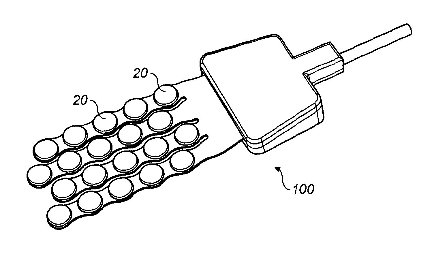
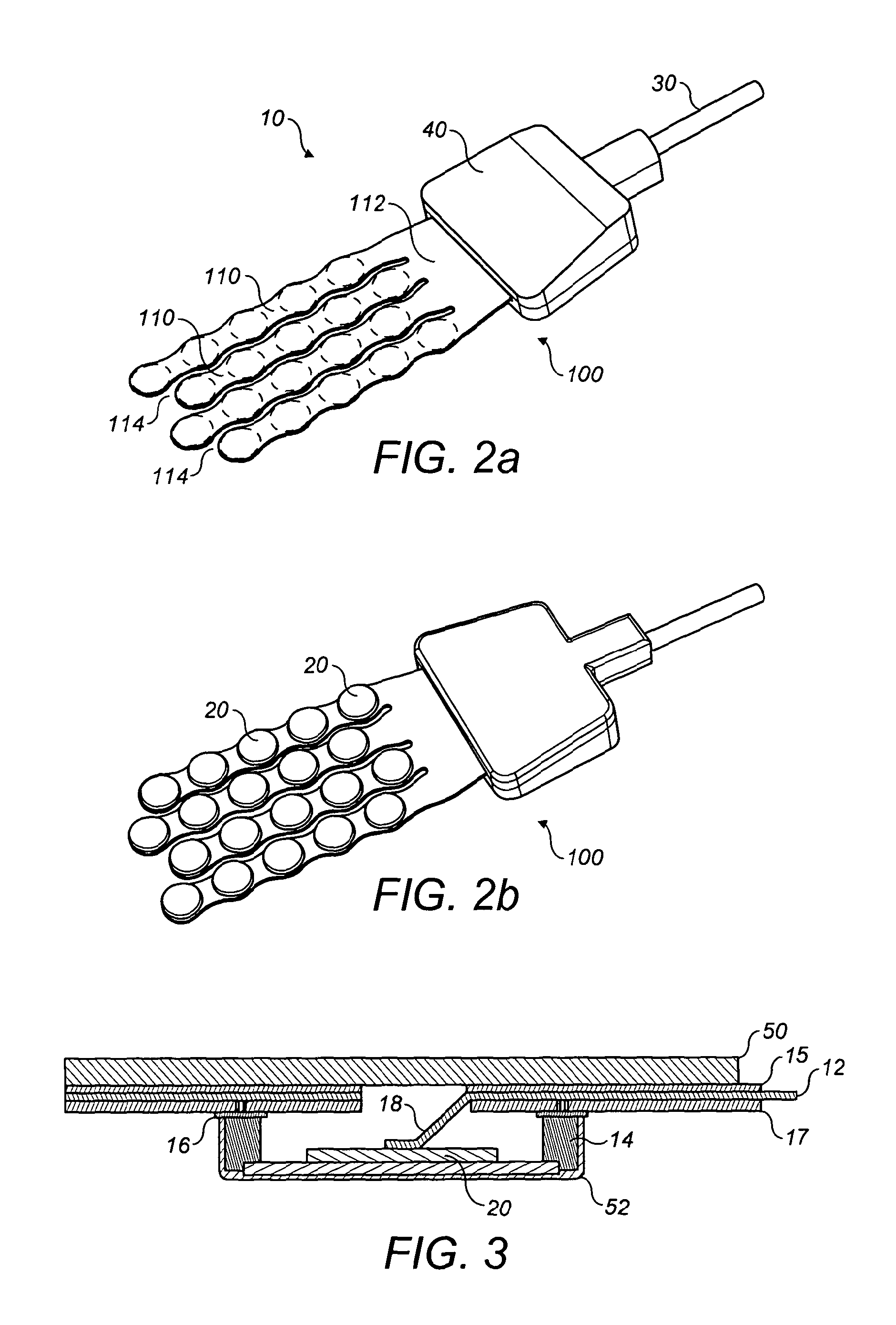
[0045]The invention is for a flat, flexible PCB 10 (flexi-PCB) which allows the mounting and electrical drive of one or more dual-frequency ultrasonic transducers 20. The combination of the transducers 20 and the flexi-PCB 10 then forms a flexible patch 100 which is capable of applying ultrasonic energy over an area in a flexible format which can form to allow effective contact on a 3D surface.

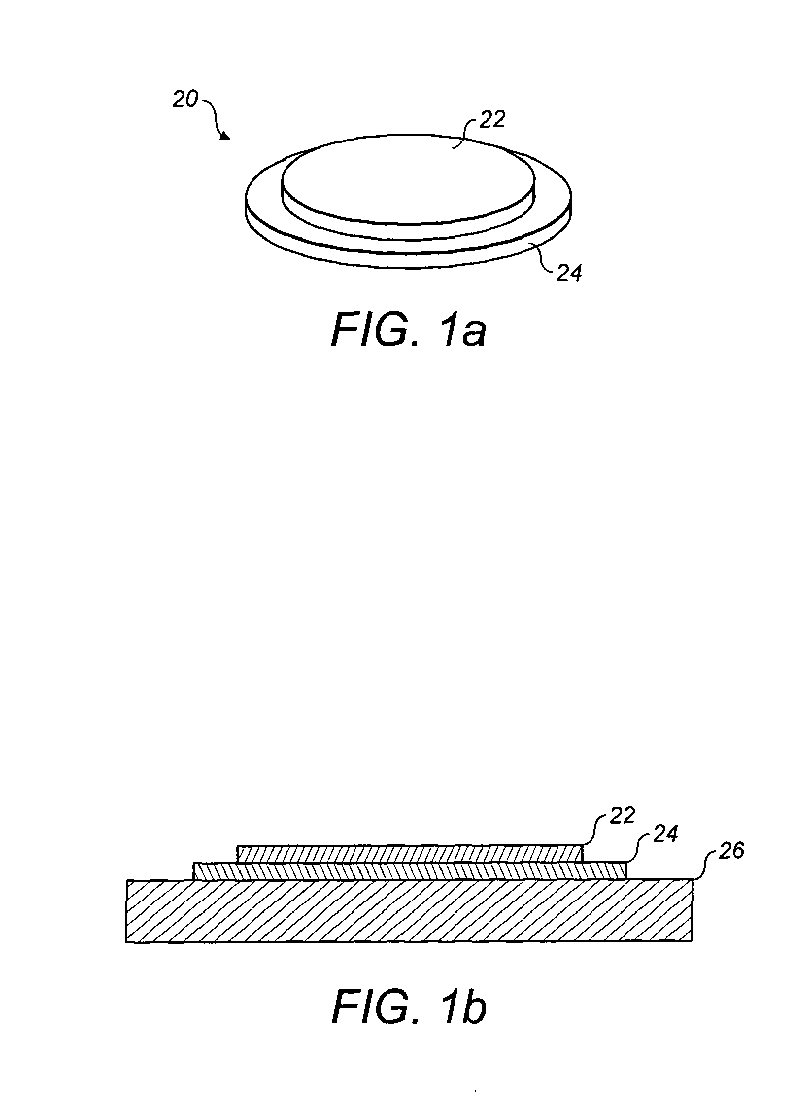
[0046]FIGS. 1a and 1b show a typical structure for a dual-frequency transducer 20, which comprises a piezo-electric, circular plate 22 bonded concentrically to a circular plastic or metal substrate 24. This construction allows the generation of acoustic energy at two different frequencies. The transducer construction used to generate the double frequency is to have a single device (the ‘transducer’ 20) vibrate in both bending mode (for the low frequency, 50 kHz) and thickness mode (for the high frequency, 3 MHz). The transducer 20 is a “unimorph”, in other words a piezo-electric plate 12 bonde...


PUM


Abstract

An ultrasound transducer patch (100) comprises an array of ultrasound transducers (20) mounted to a flexi-PCB (10) containing multiple tracks (12). Each transducer (20), or a sub-group of the transducers is electrically connected to first and second of the multiple tracks. The flexi-PCB (10) is configured, such as by virtue of cut-out portions (114, 414) or by inherent elasticity, to be bendable a out non-parallel axes. The enables the patch (100) to readily conform to a complex 3D surface such as a portion of a patient's face to ensure efficient transmission of ultrasound energy to a desired area of treatment.

Description

FIELD OF THE INVENTION[0001]This invention relates generally to the mounting and wiring of ultrasonic transducers in an array to a patch for the delivery of ultrasound for dermal and transdermal applications. More particularly, the application relates to the mounting and wiring of such a transducer array by use of a flexi-PCB.BACKGROUND TO THE INVENTION[0002]Traditionally, ultrasound has been applied through hand-held transducer probes / heads in diagnostic and therapeutic scenarios. The ‘head’ has to be continuously moved for both practical and safety reasons. In diagnostic scanning, dynamic images are displayed on a screen and movement allows the object to be viewed from multiple angles. The time averaged intensities are lower in diagnostic ultrasound but nevertheless constant movement also minimises cumulative ultrasound exposure of a given volume of soft or hard tissue. Therapeutic ultrasound (e.g. physiotherapy) utilises higher (averaged) intensities of ultrasound and is employed...

Claims


Application Information

Patent Timeline
Patent Type & Authority Applications(United States)
IPC IPC(8): A61N7/00
CPCG10K11/004B06B1/0629A61B8/4236
Inventor POLLOCK, NEILGALLUZZO, PAUL MARKCORTHORN, GRANT
Owner CAREWEAR CORP
Why Eureka
Try Eureka