Flexiblel ight-emitting unit and its making process

A manufacturing method and a flexible technology, which are applied to semiconductor devices of light-emitting elements, lighting devices, components of lighting devices, etc., can solve the problem of unsatisfactory lighting effects, difficulties in the direction of light sources of LED lighting components 2 being in the same direction, and LED luminous body It is not easy to install and fix, etc., to achieve the best tensile strength and flexibility, easy to install and fix, fast and easy to insert and fix

Inactive Publication Date: 2003-11-05
HAYASHIBARA BIOCHEMICAL LAB INC
View PDF0 Cites 13 Cited by
  • Summary
  • Abstract
  • Description
  • Claims
  • Application Information

AI Technical Summary

Problems solved by technology

[0004] Furthermore, when installing a commonly used LED illuminant, it is difficult to keep the light source direction of the LED lighting assembly 2 in the same direction as long as it is slightly deflected; that is, the LED lighting assembly 2 will be slightly deflected at an angle on the X-Z plane, Or there is a slight angle deflection on the Y-Z plane, so that the direction of the light source of the LED lighting assembly 2 is scattered; therefore, it is not easy to install and fix the commonly used LED illuminants, and the luminous effect is not ideal

Method used


Image

  • Flexiblel ight-emitting unit and its making process
  • Flexiblel ight-emitting unit and its making process
  • Flexiblel ight-emitting unit and its making process

Examples


Embodiment Construction

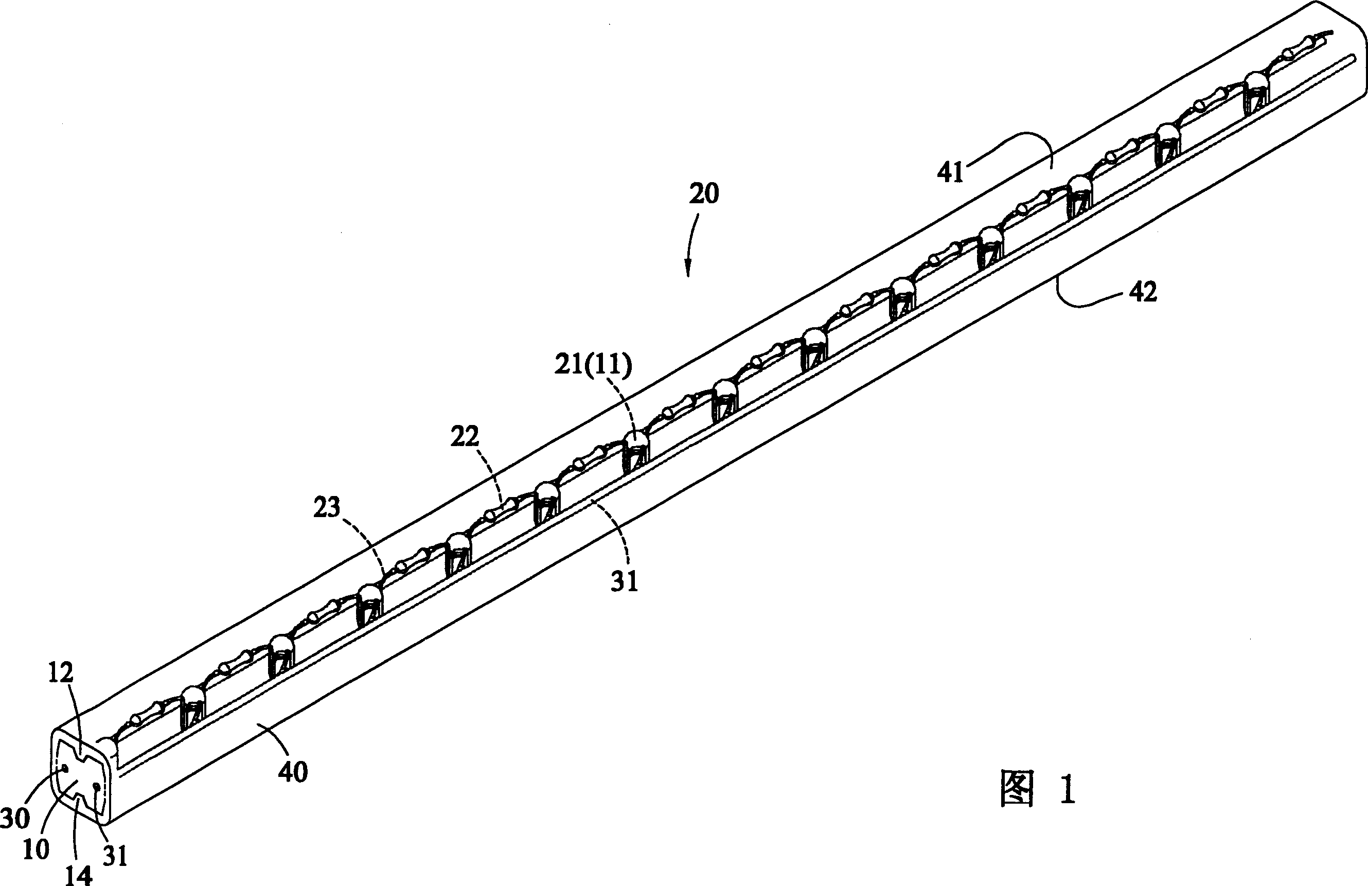
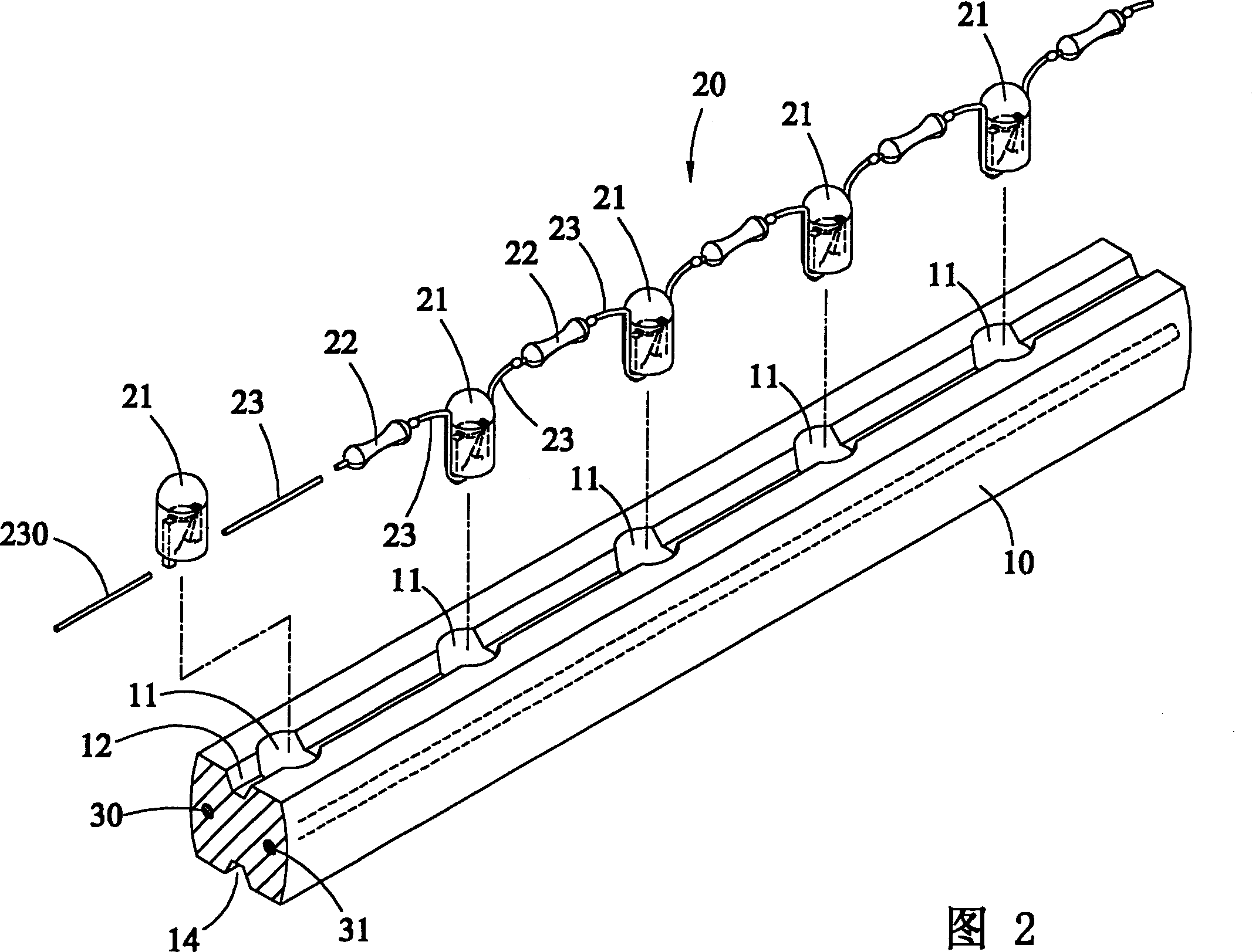
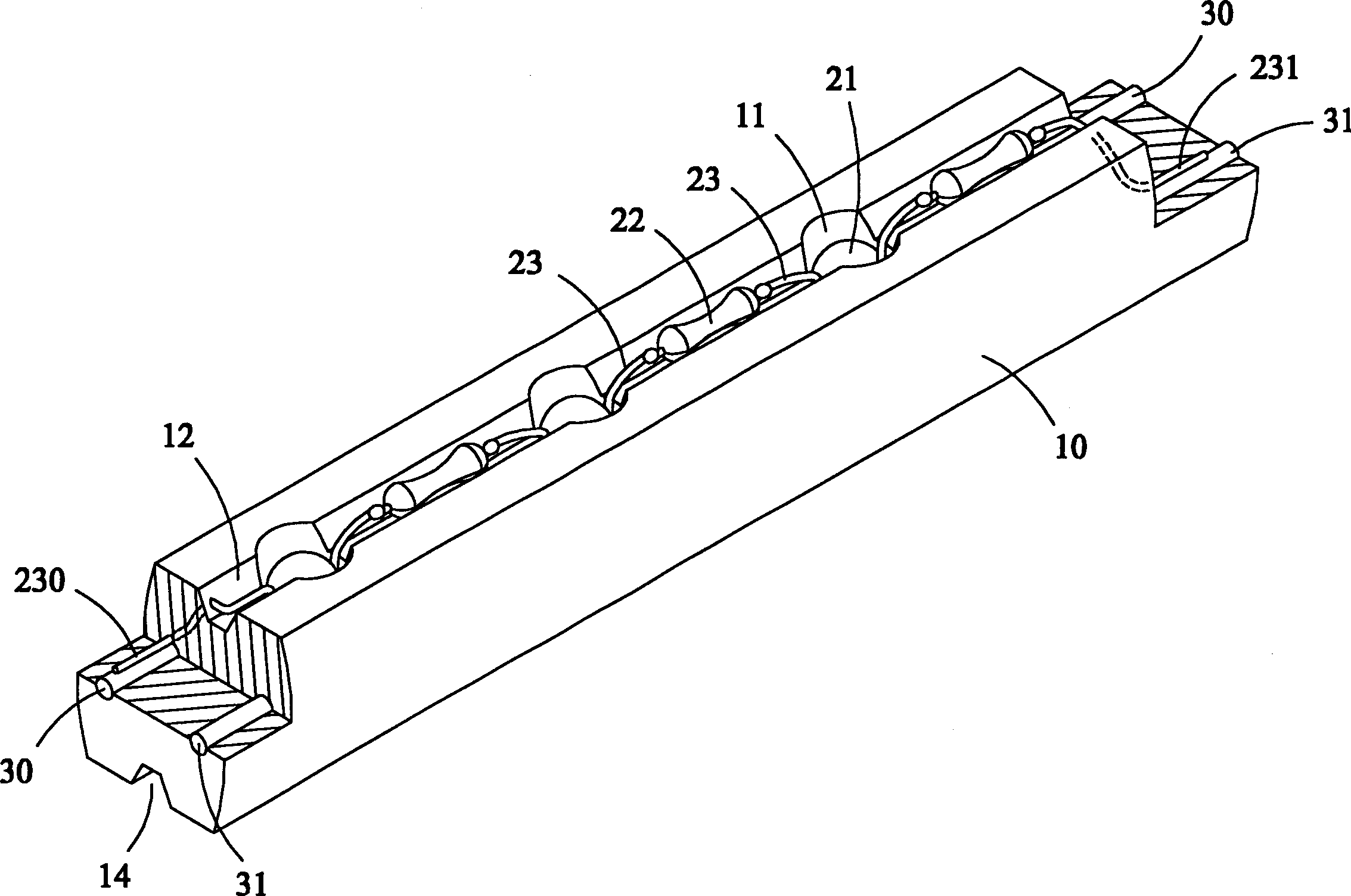
[0037] Figure 1 to image 3 As shown, the device of the present invention includes an inner layer fixing seat 10, an LED light string group 20, a pair of main wires 30, 31, and an outer layer fixing body 40; wherein, the inner layer fixing seat 10, the LED light string Group 20, the three-dimensional diagram of the main lines 30, 31, and the outer layer of fixed body 40, etc., as shown in Figure 1; the detailed three-dimensional decomposition of the LED light string group 20 and the inner layer of the fixing seat 10, as shown in Figure 2 ; Part of the three-dimensional representation of the LED lamp string group 20 arranged on the inner layer fixing base 10, as shown in detail image 3 Shown:

[0038] The inner layer fixing seat 10 is a strip-shaped transparent or translucent colloid, and several fixing holes 11 are equidistantly arranged, the top surface has an upper groove 12, and the bottom surface also has a lower groove 14, so that The inner layer fixing seat 10 forms a...


PUM


Abstract

The flexible light-emitting unit includes one inner layer fixing seat, one LED lamp string, one pair of wires and one outer fixing body. Welded serially connected LED lamp string is inserted into the holes of the pre-formed inner fixing seat, connected to one pair of embedded wires electrically, pressed and coated with one outer fixing body. The said making process results in equidistantly laidlight sources and identical light source direction.

Description

technical field [0001] The present invention relates to a flexible luminous body device and its manufacturing method (1), especially to a luminous body applicable to LEDs. In the manufacturing method, a preformed inner layer (Inner layer) fixing base is used to place the The LED light string groups after welding in series are inserted into the fixing holes of the inner layer fixing seat one by one, and the LED light string group is connected with a pair of main wires (Main wire) embedded in the inner layer fixing seat to conduct electricity, and then formed by extrusion Processing, and wrapping an outer layer (Jacket) fixed body, can make the light source equidistant layout, and the direction of the light source is consistent. Background technique [0002] Commonly used LED illuminants, such as Figure 7 As shown, generally one end of the wire 3 is welded to a pin 2a of the LED lighting assembly 2 first, and the wire 3 is bent through the side of the LED lighting assembly 2,...

Claims


Application Information

Patent Timeline
Patent Type & Authority Applications(China)
IPC IPC(8): F21V19/00F21S2/00F21S4/00F21Y101/02H01L33/00
CPCF21S4/26F21Y2115/10
Inventor 林原
Owner HAYASHIBARA BIOCHEMICAL LAB INC
Why Eureka
Try Eureka