Discharge lamp igniter device and projector device

A technology for lighting devices and discharge lamps, which is applied to projection devices, the use of gas discharge lamps, lighting devices, etc., and can solve the problems of unrealized discharge lamp lighting devices, complicated current control circuits, and reduced reliability.

Inactive Publication Date: 2003-12-31
SONY CORP
View PDF0 Cites 7 Cited by
  • Summary
  • Abstract
  • Description
  • Claims
  • Application Information

AI Technical Summary

Problems solved by technology

But in this case, the current control circuit is complicated, increasing the cost of the discharge lamp lighting device and reducing its reliability
[0007] Therefore, an inexpensive and highly reliable discharge lamp lighting device capable of a long service life has not yet been realized.

Method used


Image

  • Discharge lamp igniter device and projector device
  • Discharge lamp igniter device and projector device
  • Discharge lamp igniter device and projector device

Examples


Embodiment approach

[0031] Specific embodiments of the present invention will be described below with reference to the accompanying drawings.

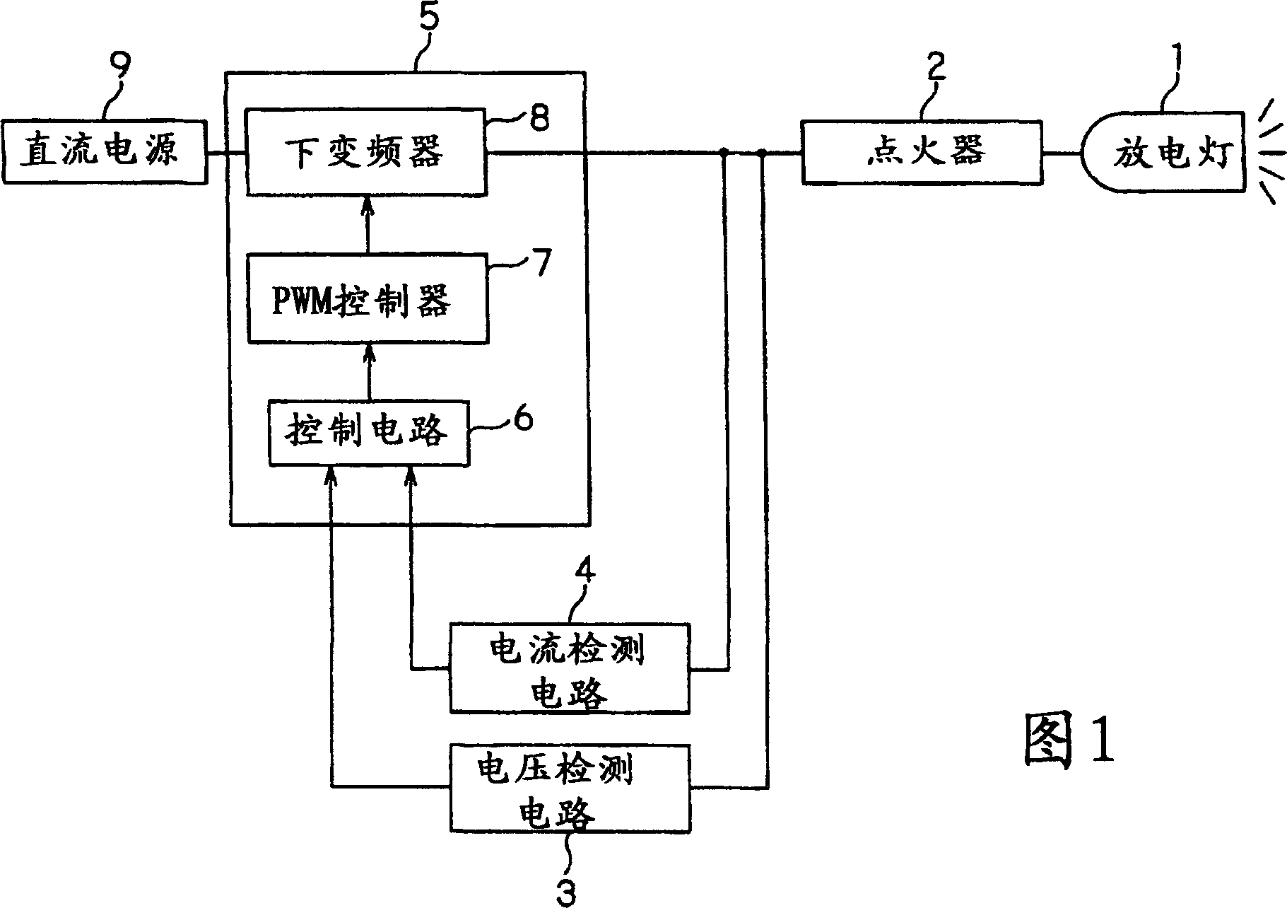
[0032] 1 is a block diagram showing a schematic structure of an embodiment of the present invention applied to a discharge lamp lighting device;

[0033] As shown in FIG. 1, the discharge lamp lighting device to which the present invention is applied has an igniter 2 as a starting device for applying a starting voltage to a discharge lamp 1 when starting 1 and thereby lighting the discharge lamp; as a voltage A voltage detection circuit 3 of the detection means for detecting a voltage applied to the discharge lamp 1; a current detection circuit 4 as the current detection means for detecting the current flowing through the discharge lamp 1; and a current control circuit part as the current control means 5. It is used to control the current flowing through the discharge lamp 1 (or to control the power supplied to the discharge lamp 1) according to the detec...


PUM


Abstract

A discharge lamp igniter for igniting a discharge lamp (1) comprises an igniter (2) serving as a starting means for igniting the discharge lamp (1) by applying a starting voltage to the discharge lamp (1) at starting the discharge lamp (1), a voltage determining circuit (3) for determining the voltage of the discharge lamp (1), and a current control circuit part (5) for controlling the current supplied to the discharge lamp (1) according to the result of the determination of the voltage determining circuit (3). After the ignition, the current control circuit part (5) starts the control of the current supplied to the discharge lamp (1) according to the result of the determination by the voltage determining circuit (3) and continuously varies the current supplied to the discharge lamp (1) at a predetermined rate of increase. In such a way, an inexpensive discharge lamp igniting device excellent in reliability and leading to a prolonged life of the discharge lamp (1) is provided.

Description

technical field [0001] The present invention relates to a discharge lamp lighting device and a projector for lighting a discharge lamp. Background technique [0002] Discharge lamps are widely used in different fields, such as being used as a light source for LCD projectors and the like. In the conventional current control method, when such a discharge lamp is lit, its current value is fixed at a value about 1.5 to 2 times the steady-state current of the discharge lamp immediately after the lamp lighting switch is turned on. , and after a predetermined time elapses, that is, when the discharge state of the discharge lamp is stable and the voltage of the discharge lamp rises to a predetermined level, its current decreases and the steady-state current gradually recovers. [0003] However, in the current control method as described above, since a large current larger than the steady-state current flows through the discharge lamp every time the discharge lamp is lit, the electr...

Claims


Application Information

Patent Timeline
Patent Type & Authority Applications(China)
IPC IPC(8): H05B41/288H05B41/292H05B41/38
CPCH05B41/2882Y02B20/208H05B41/2928H05B41/388Y02B20/00
Inventor 铃木敏夫
Owner SONY CORP
Why Eureka
Try Eureka