
Multii-directional input device

A multi-directional input and guide hole technology, applied in emergency protection devices, electrical components, electric switches, etc., can solve problems such as increased operating force, deteriorated operability of the operating body, and low self-weight

Inactive Publication Date: 2004-02-18
ALPS ALPINE CO LTD
View PDF0 Cites 8 Cited by
  • Summary
  • Abstract
  • Description
  • Claims
  • Application Information

AI Technical Summary

Problems solved by technology

[0009] However, the above-mentioned conventional multi-directional input device is because its structure is that the driving part of the operating body is accommodated in the inside of the casing, and the push button switches for tilting detection and lifting detection are arranged between the driving part and the inner bottom surface of the casing. Therefore, the height space for the coil spring is limited by the internal space of the housing. It is actually very difficult to install a coil spring with a large elastic force in such a limited space.
In such a structure, there is not much problem when the weight of the operating body is not too large, but, for example, when used as a multi-directional input device for a vehicle, for the purpose of improving operability, a long operating axis is set. In this case, since the overall weight of the operating body increases, it cannot be supported by the elastic force of the coil spring, so there is a problem that the operating body in the non-operating state shakes
[0010] Furthermore, assuming that the elastic force can be increased by design changes such as increasing the wire diameter of the above-mentioned coil spring, another problem arises, that is, since the elastic force per unit displacement is increased, even if the shaking of the operating body can be prevented, it will not be possible. Excessively increase the operating force and deteriorate the operability of the operating body

Method used


Image

  • Multii-directional input device
  • Multii-directional input device
  • Multii-directional input device

Examples


Embodiment Construction

[0028] Embodiment of the invention

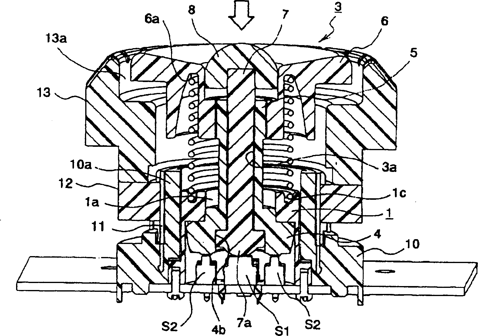
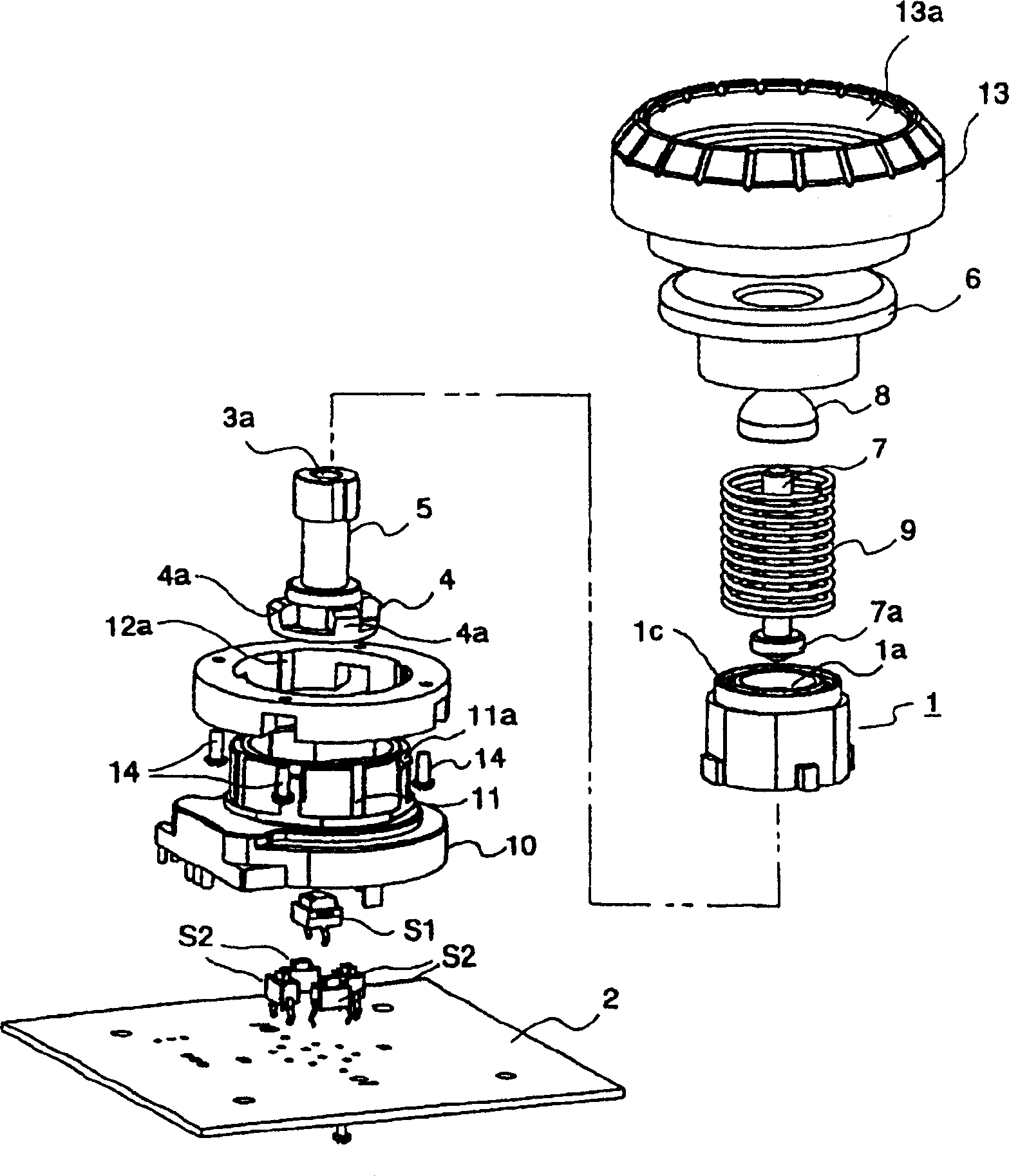
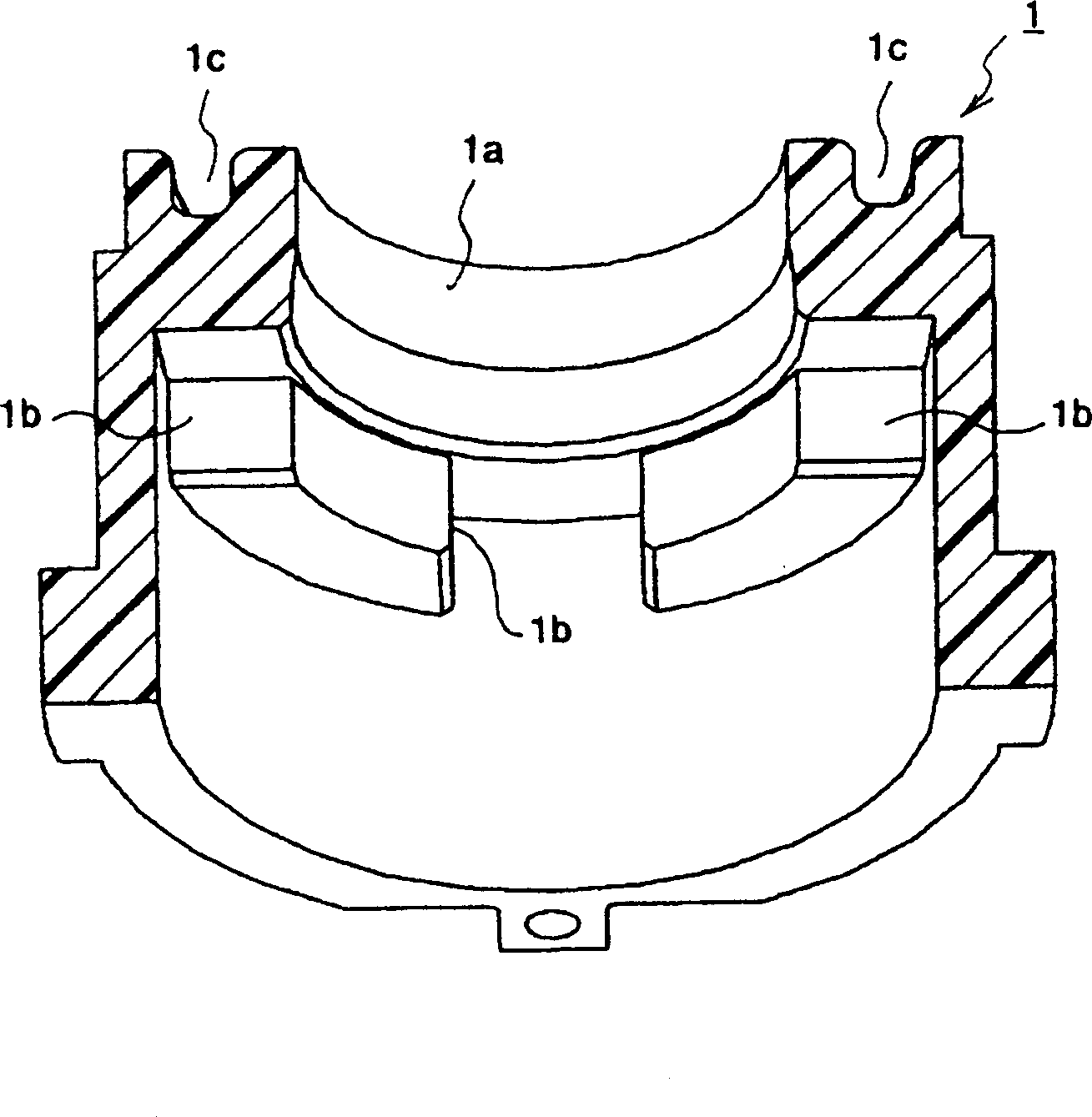
[0029] Embodiments of the present invention will be described in detail below with reference to the drawings. figure 1 It is a cross-sectional view of a multi-operation type electric component incorporating the multi-directional input device according to the embodiment. figure 2 It is an exploded perspective view of a multi-operation type electric component incorporating the multi-directional input device according to the embodiment. image 3 is a cross-sectional view of a casing included in the multi-directional input device. Figure 4 It is an explanatory diagram of the operation of the multi-directional input device.

[0030] The multi-operation electric parts shown in these figures are composed of a combination of an inner multi-directional input device and an outer rotary encoder, and the multi-directional input device and the rotary encoder can be operated independently.

[0031] First, the inner multidirectional input device will...


PUM


Abstract

A multidirectional input device to surely prevent looseness without sacrificing operability even if the size of an operation body and the weight thereof are increased is provided with: a housing (1); the operation body (3) having a drive part (4), a first operation shaft (5) and an operation knob (6) mounted to the tip of the first operation shaft (5); a second operation shaft (7) vertically movably held in a guide hole (3a) formed in the operation body (3); and a coil spring (9) mounted between the upper surface of the housing (1) and the operation knob (6). By pressing an arbitrary position of the operation knob (6) to tilt the first operation shaft (5), the drive part (4) selectively turns on a plurality of push-switches (S2) corresponding to the tilting direction, and by pressing a push-knob (8) mounted to the upper end of the second operation shaft (7) downward, the lower end (7a) of the second operation shaft turns on a push-switch (S1).

Description

technical field [0001] The present invention relates to a multi-directional input device used in input operation units of various electronic devices, and more particularly to a multi-directional input device capable of performing different input actions such as tilting operation and pressing operation. Background technique [0002] In the past, the main components of this multi-directional input device were: [0003] The shell has an opening on its upper surface, and a push button switch for lifting detection and a plurality of push button switches for dumping detection are respectively arranged in the center of the inner bottom surface and its surroundings; [0004] An operating body, which has a guide hole penetrating up and down, and is composed of a driving part housed in the housing and a first operating shaft connected to the driving part and protruding from the opening of the housing; [0005] The second operating shaft is fitted and held in the guide hole of the ope...

Claims


Application Information

Patent Timeline
IPC IPC(8): H01H25/04H01H25/06H01H89/00
Inventor 石川新治
Owner ALPS ALPINE CO LTD
Learn More