Projection optical system, projection image display device and image display system
What is AI technical title?
AI technical title is built by Patsnap AI team. It summarizes the technical point description of the patent document.
一种图像显示装置、投射光学的技术,应用在投射光学系统领域,能够解决无法配置多个透镜等问题
Inactive Publication Date: 2004-03-03
CANON KK
View PDF5 Cites 15 Cited by
Summary
Abstract
Description
Claims
Application Information
AI Technical Summary
This helps you quickly interpret patents by identifying the three key elements:
Problems solved by technology
Method used
Benefits of technology
Problems solved by technology
This is because the distance from the image display panel to the pupil plane is equivalent to the focal length, and multiple lenses cannot be arranged, and the lens must be arranged between the pupil plane and the screen.
Method used
Image
Click on the blue label to locate the original text in one second.
Reading with bidirectional positioning of images and text.
Examples
no. 1 Embodiment
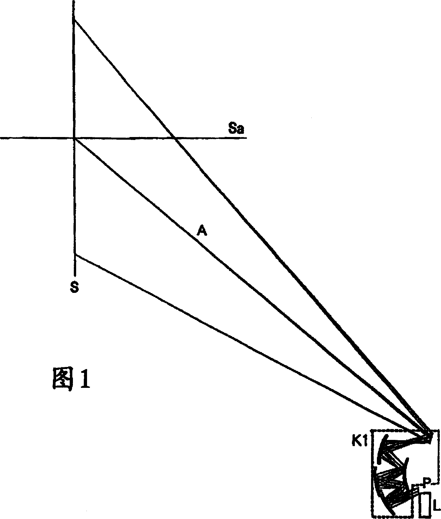
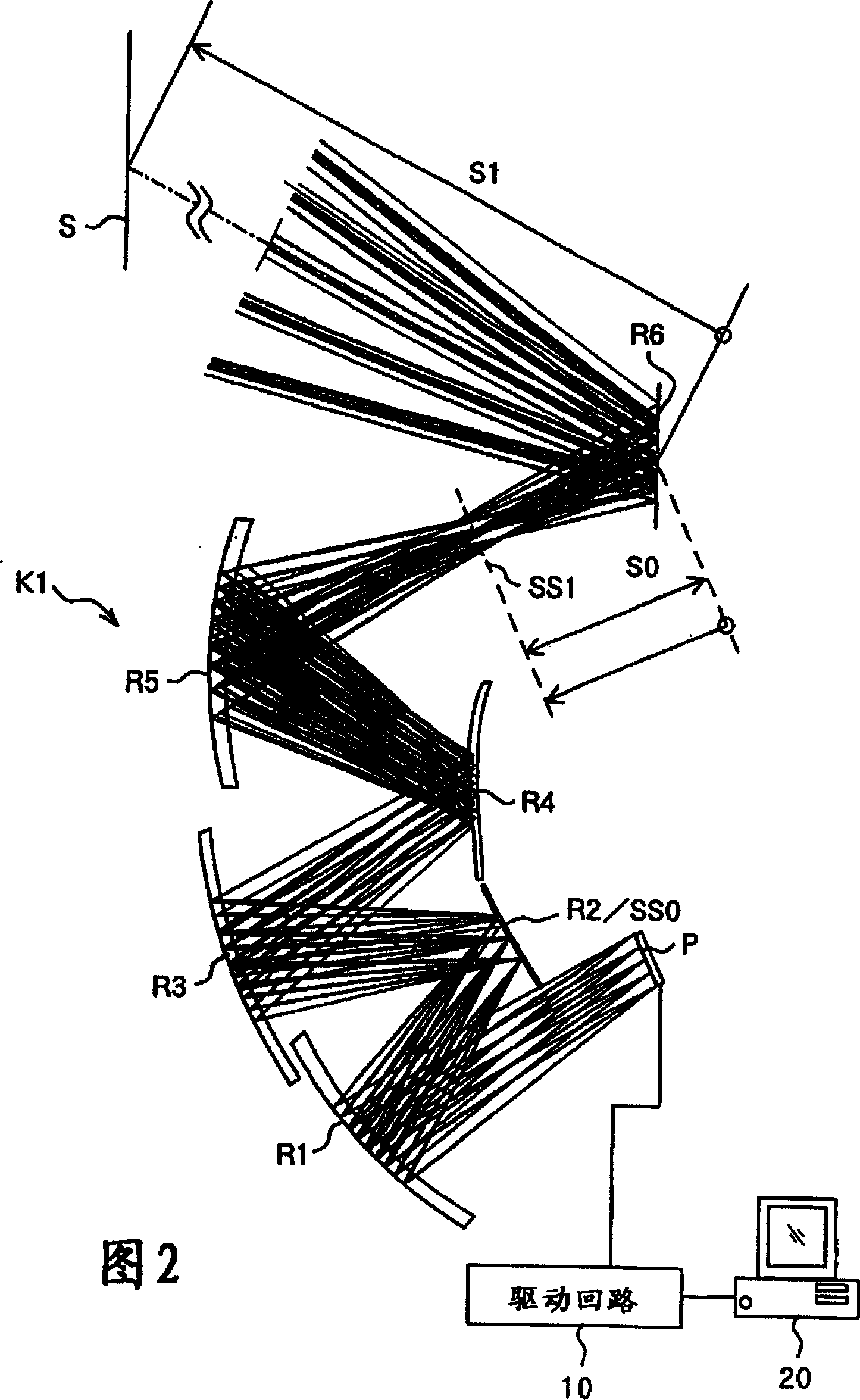
[0060] FIG. 1 is a partial schematic diagram of an entire optical system of a projector (projection type image display device) used as a projection optical system according to a first embodiment of the present invention. In addition, the projection optical system is enlarged and shown in FIG. 2 .
[0061] In these figures, P is an image forming element, and a reflective dot matrix liquid crystal or a digital micromirror device or the like can be used.
[0062] On the image forming element, as shown in FIG. 2, a drive circuit 10 is connected. Image information is input from an image information supply device such as a personal computer, video recorder, television, DVD player, mobile phone, electromagnetic wave receiving device (wired, wireless), etc. to the drive circuit 10, and the drive circuit 10 drives the image forming element P to display thereon The original image corresponding to the input image information. Thereby, an image display system using a projection type ima...
no. 2 Embodiment
[0120] Figure 5 Middle is a partial schematic view of the entire optical system of the projector used as the projection optical system of the second embodiment of the present invention. also, Image 6 Middle magnification shows the projection optics.
[0121] In these figures, P is an image forming element, and a reflective dot matrix liquid crystal or a digital micromirror device or the like can be used.
[0122] L is an illumination system for irradiating light to the image forming element P. The illumination system L is composed of a lamp, a condenser lens, a filter for selecting a wavelength, and the like.
[0123] K is a projection optical system that guides the light modulated by the image forming element P to the screen S, and forms an image on the screen S. The refractive optical system is composed of a plurality of coaxial refracting lenses sequentially from the image forming element P side. K2, and the reflective optical system K3 using an off-axis system.
[0...
PUM
Abstract
A projection optical system which has a short projection distance and a compact structure, and allows oblique projection. The projection optical system projects luminous flux from an image forming element for forming an original image onto a projection surface which is oblique to a central principal ray which is a principal ray of luminous flux traveling from the center of the original image to the center of a finally formed image. The system includes a plurality of reflecting surfaces each having a curvature. In addition, the projection optical system satisfies a predetermined expression (1).
Description
technical field [0001] The present invention relates to a projection optical system used in a projection type image display device such as a projector. Background technique [0002] Traditionally, image forming elements such as liquid crystal display panels are illuminated by light from a light source, and the transmitted light or reflected light modulated by the image forming element is enlarged and projected on a projected surface such as a screen by a projection optical system. Projectors have been designed in various ways. [0003] Some of the projection optical systems used in such projectors are capable of projecting from an oblique direction to the screen (hereinafter referred to as oblique projection) in order to increase the size of the projected image and reduce the thickness of the device. [0004] For example, in Japanese Unexamined Patent Application Publication No. 1993-100312, a wide-angle lens with a large field of view is proposed as a projection optical sy...
Claims
Application Information
Patent Timeline
Application Date:The date an application was filed.
Publication Date:The date a patent or application was officially published.
First Publication Date:The earliest publication date of a patent with the same application number.
Issue Date:Publication date of the patent grant document.
PCT Entry Date:The Entry date of PCT National Phase.
Estimated Expiry Date:The statutory expiry date of a patent right according to the Patent Law, and it is the longest term of protection that the patent right can achieve without the termination of the patent right due to other reasons(Term extension factor has been taken into account ).
Invalid Date:Actual expiry date is based on effective date or publication date of legal transaction data of invalid patent.

