Projection optical system unit, projection optical system, and projection optical apparatus

a technology of projection optical system and projection optical apparatus, which is applied in the direction of optics, projectors, instruments, etc., can solve the problems of insufficient progress of the reduction of the size and brightness of the very short projection distance projector, and the increase of the efficiency of the projector

Active Publication Date: 2021-01-12
RICOH KK
View PDF55 Cites 0 Cited by
  • Summary
  • Abstract
  • Description
  • Claims
  • Application Information

AI Technical Summary

Benefits of technology

[0004]In order to achieve a very short projection distance with a small size, projectors employing a curved mirror have been proposed. Some of the projectors can achieve a very short projection distance by employing a curved mirror in combination with a refractive optical system.

Problems solved by technology

However, existing technologies have a problem in that, even if it is possible to realize a very short projection distance with a projection optical system, reduction in size and increase in brightness (increase in efficiency) of a very short projection distance projector do not sufficiently proceed.

Method used


Image

  • Projection optical system unit, projection optical system, and projection optical apparatus
  • Projection optical system unit, projection optical system, and projection optical apparatus
  • Projection optical system unit, projection optical system, and projection optical apparatus

Examples


first embodiment

[0035]Specific structures of a projection optical system unit according to a first embodiment will be described.

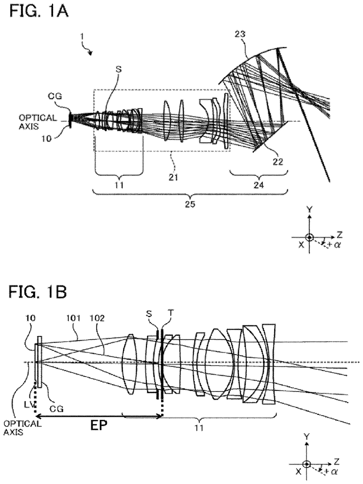
[0036]FIGS. 1A and 1B illustrate an example of a projection optical system unit according to the first embodiment. FIG. 1A illustrates an example of the structure of a projection optical system unit 1 including an image display element 10 and a projection optical system 25. FIG. 1B is an enlarged view of the image display element 10 illustrated in FIG. 1A and a plurality of lenses 11 included in a refractive optical system 21 of the projection optical system 25. The image display element 10 includes an image forming portion LV, which is, for example, a light valve such as a DMD, a transmissive liquid crystal panel, or a reflective liquid crystal panel. The image forming portion LV is a “portion that forms an image to be projected”. If the image display element 10 is an element that does not emit light, such as a DMD, image information formed in the image forming portion LV...

second embodiment

[0071]Next, a projection optical apparatus according to a second embodiment will be described. The projection optical apparatus includes the projection optical system unit according to the first embodiment. Therefore, in the second embodiment, descriptions of portions that are same as those of the first embodiment will be omitted, as appropriate, and, differences from the first embodiment will be mainly described.

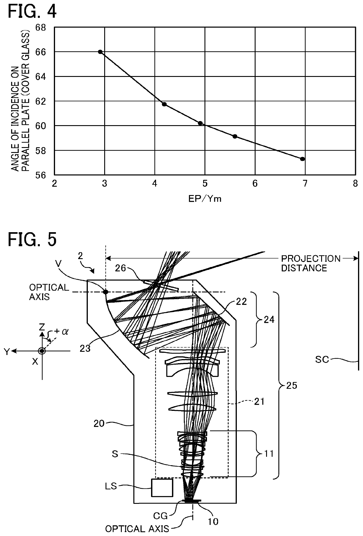
[0072]FIG. 5 illustrates an example of a projection optical apparatus according to the second embodiment. FIG. 5 illustrates the internal structure of the projection optical apparatus.

[0073]A projection optical apparatus 2 illustrated in FIG. 5 includes, in a housing 20, an illumination optical system LS, the image display element 10, the parallel plate CG, the projection optical system 25, and a dustproof glass 26. The projection optical system 25 includes the refractive optical system 21, and the reflective optical system 24 including a plane mirror (reflective surface) 2...

first modification

of Second Embodiment

[0123]A modification of the second embodiment will be described. In the following description, differences from the second embodiment will be mainly described, and elements common to the second embodiment and the modification will not be illustrated and described, as appropriate.

[0124]FIG. 13 illustrates an example of a projection optical apparatus according to a first modification of the second embodiment. FIG. 13 illustrates the internal structure of the projection optical apparatus. In the refractive optical system 21, a lens arrangement and a light path in a case of 100 inches are illustrated. The first modification differs from the projection optical apparatus according to the second embodiment in the lens structure of the refractive optical system 21.

[0125]FIG. 14 illustrates an example of the lens structure of the refractive optical system 21 according to the first modification and an example of the lens arrangement in accordance with a focus. FIG. 14 illu...


PUM


Abstract

A projection optical system satisfies θ1≥15 (deg) and 3<EP / Ym<7. θ1 is a maximum inclination angle of the reflective surface of each of the micromirrors with respect to the line normal to the image display surface; EP is an entrance pupil distance of the projection optical system; and Ym is a maximum distance in a plane from an optical axis to a point on the image display surface, the plane being a plane in which a light ray propagating from a center of the image display surface toward the projection surface through a center of an aperture stop of the projection optical system exists, the optical axis being an axis shared by a largest number of the plurality of lenses of the projection optical system, the point corresponding to an image on the projection surface.

Description

CROSS-REFERENCE TO RELATED APPLICATION[0001]This patent application is based on and claims priority pursuant to 35 U.S.C. § 119(a) to Japanese Patent Application No. 2018-050356, filed on Mar. 19, 2018 in the Japan Patent Office, the entire disclosure of which is hereby incorporated by reference herein.BACKGROUNDTechnical Field[0002]Embodiments of the present disclosure relate to a projection optical system unit, a projection optical system, and a projection optical apparatus.Description of the Related Art[0003]In recent years, image display elements that project an image generated by a digital micromirror device (DMD) or a liquid crystal panel onto a screen are widely used. In particular, recently, demand for front-projection projectors that can display a large image at a short projection distance has been increasing.[0004]In order to achieve a very short projection distance with a small size, projectors employing a curved mirror have been proposed. Some of the projectors can achie...

Claims


Application Information

Patent Timeline
Patent Type & Authority Patents(United States)
IPC IPC(8): G03B21/28G03B21/00G02B26/08G03B21/14G02B13/16
CPCG03B21/28G02B13/16G02B26/0833G03B21/008G03B21/142
Inventor TAKANO, YOHEINAKAYAMA, HIROTOSHI
Owner RICOH KK
Why Eureka
Try Eureka