Projection optical system and image display device

A technology for projecting optical systems and images, applied in the direction of optics, projection devices, optical components, etc.

Active Publication Date: 2017-01-18
RICOH KK
View PDF9 Cites 0 Cited by
  • Summary
  • Abstract
  • Description
  • Claims
  • Application Information

AI Technical Summary

Problems solved by technology

[0004] However, none of the projection optical systems included in the projectors disclosed in Patent Documents 1 to 4 can fully meet the current miniaturization requirements.

Method used


Image

  • Projection optical system and image display device
  • Projection optical system and image display device
  • Projection optical system and image display device

Examples


Embodiment approach 1

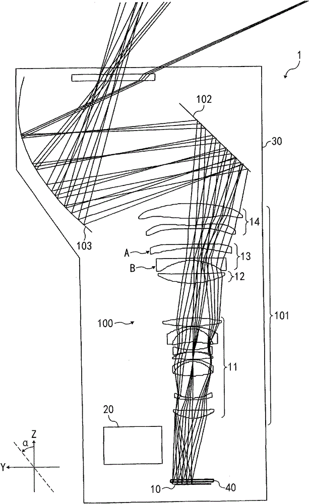
[0060] First, an embodiment of an image display device according to the present invention will be described. figure 1 It is an optical layout diagram of the image display device according to the present invention. The housing 30 of the projector 1 that is an image display device accommodates the image forming unit 10 , the parallel plate 40 , the projection optical system 100 according to the present invention, the illumination optical system 20 having a light source that emits illumination light for irradiating the image forming unit 10 , and other components required for image formation.

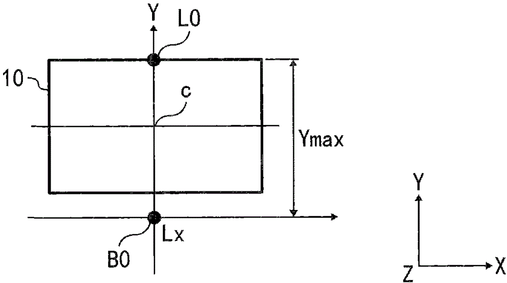
[0061] The image forming unit 10 is constituted by, for example, a DMD, a transmissive liquid crystal panel, a reflective liquid crystal panel, or the like. The image forming unit 10 in the present embodiment refers to, for example, a "portion for forming an image to be projected" in a DMD.

[0062] The parallel flat plate 40 is located near the image forming portion 10 and is a cover gl...

Embodiment 1

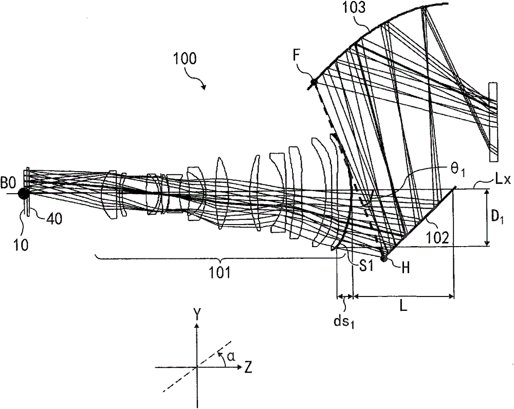
[0106] Figure 5 It is an optical layout diagram of the refractive optical system 101 involved in this embodiment. like Figure 5 As shown, the refractive optical system 101 has a first lens group 11 , a second lens group 12 , a third lens group 13 , and a fourth lens group 14 .

[0107] Figure 5 The solid line in the middle shows the movement locus of each lens group constituting the refractive optical system 101 during focusing from a long distance to a short distance. Here, the projection distance when the image size projected on the screen is 80 inches is long distance, and the projection distance when the image size is 48 inches is short distance.

[0108] The first lens group 11 is provided with the following lenses in order from one side of the image forming portion 10: a biconvex mirror with aspherical surfaces on both sides, wherein the convex surface facing the image forming portion 10 is more convex; a negative meniscus mirror, wherein the The convex surface fa...

Embodiment approach 2

[0138] Another embodiment of the image display device according to the present invention will be described below. In the following description, the same reference numerals are used for the content already described, and the description will not be repeated.

[0139] Figure 15 It is an optical path diagram of the projector 1a according to the present embodiment. Figure 15 The housing 30 of the shown projector 1a accommodates the image forming unit 10, the parallel plate 40, the refractive optical system 100a of the present invention, the illumination optical system 20, and other components necessary for image formation, wherein the illumination optical system 20 includes An illumination light source for illuminating the image forming section 10 .

[0140] The projection optical system 100a includes a refractive optical system 101a, a flat mirror 102a that is a first reflecting surface, and a curved mirror 103a that is a second reflecting surface. like Figure 15As shown, ...


PUM


Abstract

The present invention relates to a projection optical system and an image display device, and an object of the present invention is to provide a compact projection optical system with a very short projection distance. In the projection optical system, the distance L between the intersection point of the mirror surface on the side of the magnification end of the lens closest to the magnification end and the optical axis to the intersection point of the reflector (102) and the optical axis is the minimum distance L, the focal length f of the refraction optical system (101) , When the optical axis direction is the Z axis and the arrangement direction of the plane mirror (102) and the curved mirror (103) is the Y axis, the maximum distance Ymax between the optical axis and the end of the image forming part (10) on the Y axis Satisfied on the YZ plane and among them, D1 is the maximum distance from the intersection point of the ray and the mirror on the magnifying end side of the lens closest to the magnifying end to the optical axis, ds1 is the concave amount of the mirror part covered by D1, θ1 is the connecting light The angle between the line of the point with the largest distance from the optical axis and the smallest point in the intersection with the curved mirror (103) and the optical axis.

Description

technical field [0001] The present invention relates to a projection optical system for an image display device and an image display device that enlarges and projects an image on a screen. Background technique [0002] The image display device is also called a projector, and is used to project an image formed by an image forming unit on a screen, which is a projected surface. The projector includes a projection optical system that enlarges and projects the image formed by the image forming unit on the screen. The image forming section of the projector includes elements such as a Digital Micro-mirror Device (hereinafter abbreviated as DMD) or a liquid crystal panel. Among the projectors, there is a short-distance type projector, which can shorten the projection distance from the screen. In recent years, a projector that projects at an ultra-short distance can also enlarge the size of the image displayed on the screen, that is, an ultra-short-distance projector that can disp...

Claims


Application Information

Patent Timeline
Patent Type & Authority Patents(China)
IPC IPC(8): G02B27/18G02B17/08G03B21/14G03B21/28
CPCG02B17/08G02B17/0852G02B17/0896G03B21/28G02B3/04G02B5/10G02B13/16G03B21/14
Inventor 高野洋平辰野响新井伸幸中山裕俊
Owner RICOH KK
Why Eureka
Try Eureka