
Three-dimensional image display apparatus using laser beam scanning projection optical systems

a three-dimensional image and optical system technology, applied in the direction of picture reproducers, picture reproducers using projection devices, instruments, etc., can solve the problems of inconvenient wearing special glasses such as polarized glasses, inability to provide natural motion, and uneven distribution of light intensity of different projection optical systems, so as to achieve the effect of minimizing crosstalk

Active Publication Date: 2018-04-03
KOREA INST OF SCI & TECH
View PDF7 Cites 0 Cited by
  • Summary
  • Abstract
  • Description
  • Claims
  • Application Information

AI Technical Summary

Benefits of technology

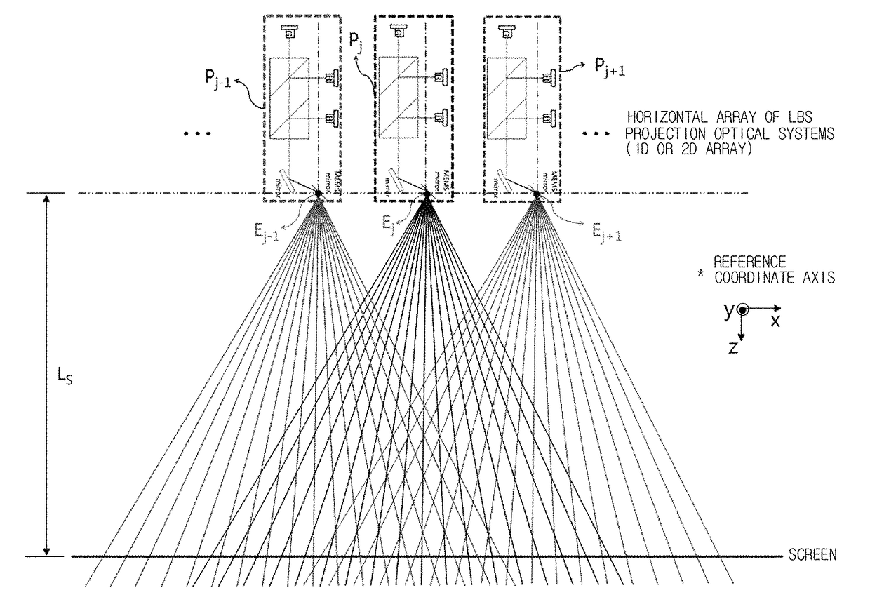
[0035]The present invention is directed to providing a three-dimensional (3D) image display apparatus that uses an array of laser beam scanning (LBS) projection optical systems in each of which a light output unit is configured to be a unit 3D pixel (or pixel line), and thus has relaxed limitations on space and size, provides hundreds of viewpoint images or more, uniformizes light intensity of viewing zones providing the respective viewpoint images, forms the same picture size on a screen with a shorter projection distance than existing projection optical systems, and minimizes crosstalk between adjacent viewpoints, so that many viewers are able to view a clear 3D image without special glasses even during a 3D spatial movement within a view range in front of the screen.

Problems solved by technology

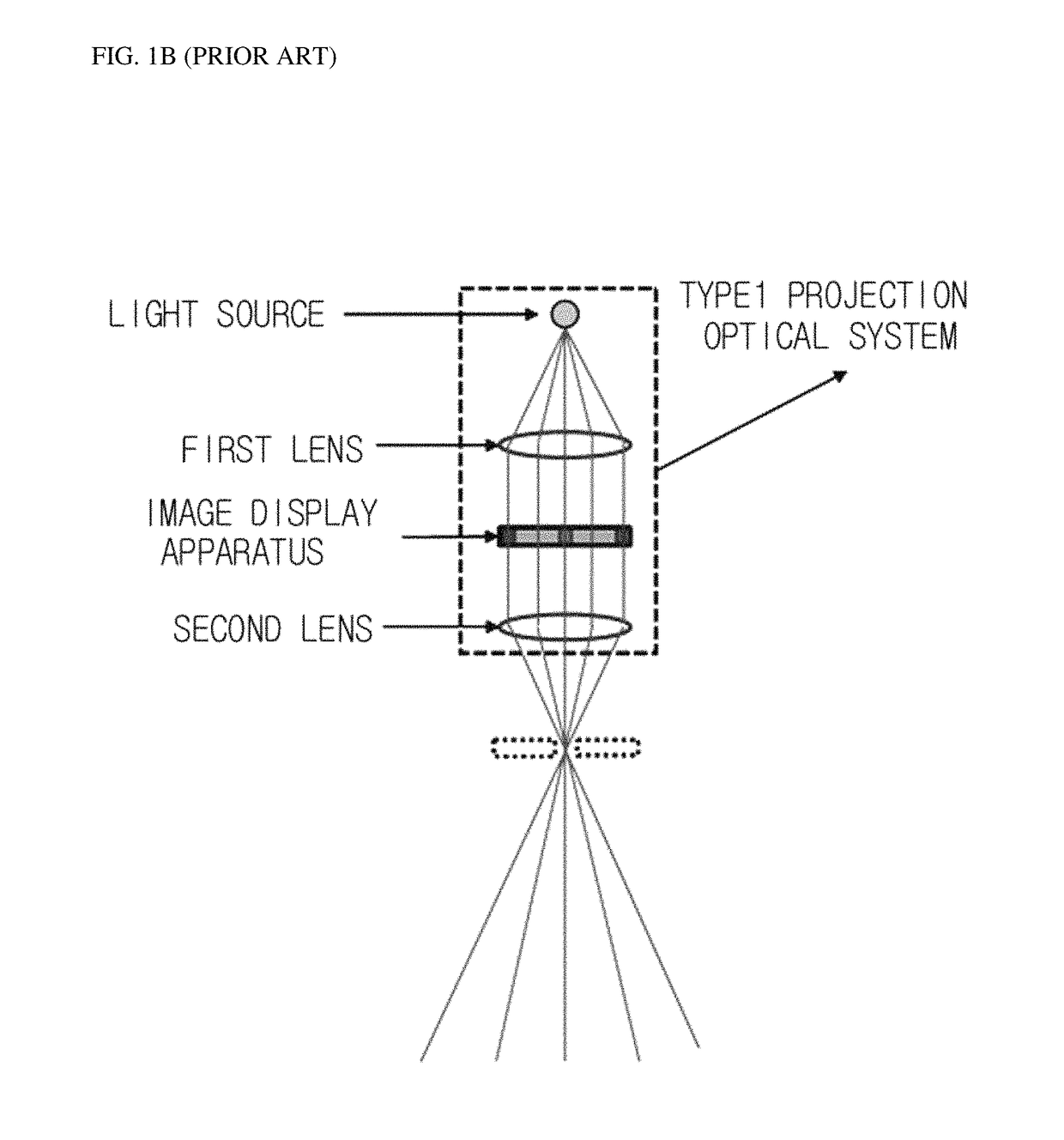
Since a 3D image display apparatus of the stereoscopic display type provides only two viewpoint images corresponding to both eyes, it is not possible to provide natural motion parallax, etc. according to movement of a viewer's position, and it is inconvenient to wear special glasses such as polarized glasses.
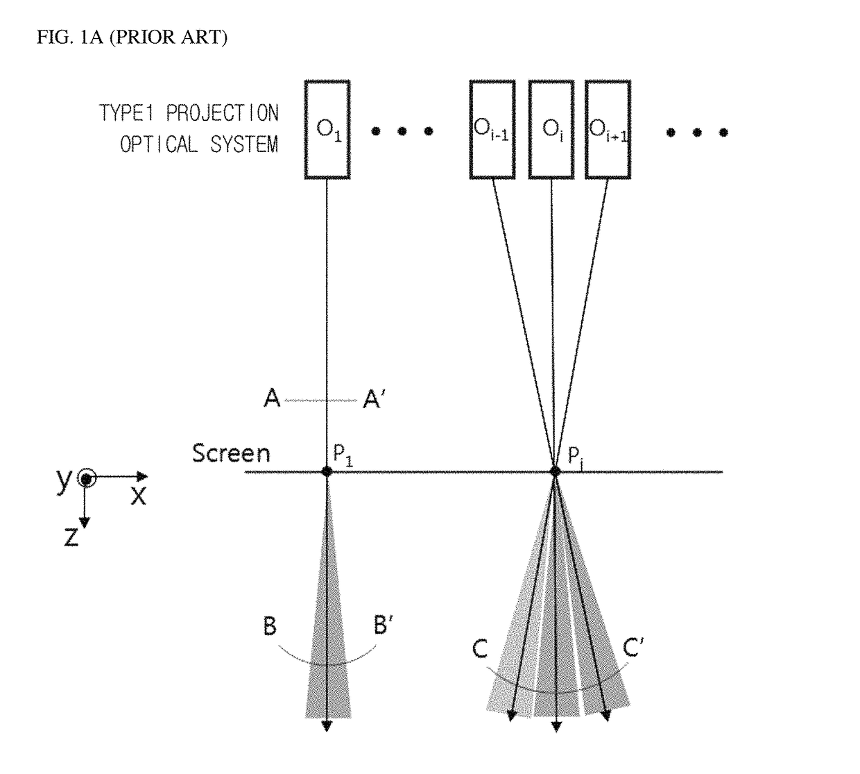
However, in this case, the distribution of intensity of rays of light generated by different projection optical systems and forming adjacent viewing zones on the same 3D pixel (or 3D pixel line) on the screen is not uniform, and the adjacent viewing zones generated from the same 3D pixel overlap each other.
Such non-uniformity of brightness of a viewing zone including viewpoint image information and crosstalk occurring due to the overlap of adjacent viewing zones mainly cause a viewer to feel tired of viewing a 3D image through such a system.
Also, the non-uniformity of brightness of a viewing zone and the crosstalk limit depth perception of a 3D image expressible through the system.
However, like the 3D system using type-1 projection optical systems, it is difficult to reduce crosstalk between adjacent viewing zones and adjust the intervals so as to maintain uniform brightness according to an angle in one viewing zone.
However, when the viewing zones do not have an ideal distribution according to an angle as shown in FIG. 5, image information of an adjacent viewing zone is seen even at the central-angle position of each viewing zone (e.g., A position in FIG. 6), thus causing a viewer who views a 3D image to feel tired.
Therefore, with the two kinds of existing technology, it is not easy to ensure the uniformity of the distribution of viewing zones while minimizing crosstalk between adjacent viewing zones formed on unit 3D pixels (or pixel lines) in a screen.
However, it is difficult to display images of hundreds of projection optical systems arranged in a 2D array on a single screen without distortion.
According to a 3D system using type-2 projection optical systems, an image is cleared formed at a position apart from each projection optical system by a determined focal length, and thus it is particularly not easy to adjust a screen size using the determined projection optical systems.
Also, a relatively long projection distance is necessary to form an image on a screen, and it is difficult to form a clear 3D pixel line in the whole area of a single screen using projection optical systems in a 2D array.

Method used


Image

  • Three-dimensional image display apparatus using laser beam scanning projection optical systems
  • Three-dimensional image display apparatus using laser beam scanning projection optical systems
  • Three-dimensional image display apparatus using laser beam scanning projection optical systems

Examples


Embodiment Construction

[0100]Exemplary embodiments of the present invention are disclosed herein. However, specific structural and functional details disclosed herein are merely representative for purposes of describing the exemplary embodiments of the present invention, and the present invention may be embodied in many alternate forms and should not be construed as limited to the exemplary embodiments of the present invention set forth herein. Accordingly, while the present invention is susceptible to various modifications and alternative forms, specific embodiments thereof are shown by way of example in the drawings and will herein be described in detail. It should be understood, however, that there is no intent to limit the present invention to the particular forms disclosed, but on the contrary, the present invention is to cover all modifications, equivalents, and alternatives falling within the spirit and scope of the present invention.

[0101]First, the basic principle of a laser beam scanning (LBS) p...


PUM


Abstract

Provided is a three-dimensional (3D) image display apparatus using laser beam scanning (LBS) projection optical systems. The 3D image display apparatus includes a plurality of LBS projection optical systems arrayed in horizontal and vertical directions, an input unit through which a 3D image signal is input, and an image signal controller configured to distribute the 3D image signal input through the input unit to the LBS projection optical systems. Each of the arrayed LBS projection optical systems has a beam-projection center point for outputting light to an outside of the LBS projection optical system, and an image projected from the beam-projection center point is a horizontal-parallax image based on the beam-projection center point.

Description

CROSS-REFERENCE TO RELATED APPLICATION[0001]This application claims priority to and the benefit of Korean Patent Application No. 2014-0107741, filed on Aug. 19, 2014, the disclosure of which is incorporated herein by reference in its entirety.BACKGROUND1. Field of the Invention[0002]The present invention relates to an auto-stereoscopic three-dimensional (3D) image display apparatus, and more particularly, to an auto-stereoscopic 3D image display apparatus for many persons in which each of many laser beam scanning (LBS) projection optical systems horizontally and vertically arranged in a two-dimensional (2D) array becomes one 3D pixel for forming a 3D viewing zone to generate a full-parallax image or each of many LBS projection optical systems horizontally and vertically arranged in a 2D array or horizontally arranged in an one-dimensional (1D) array becomes one 3D pixel line for forming a 3D viewing zone to generate a horizontal parallax image, so that the quality of a 3D image is s...

Claims


Application Information

Patent Timeline
Patent Type & Authority Patents(United States)
IPC IPC(8): G03B35/20H04N9/31G02B27/22G02B26/10G02B27/14H04N13/363
CPCH04N9/3164G02B26/101G02B27/2264G03B35/20H04N9/3147H04N13/0409H04N13/0459H04N9/3129G02B27/141H04N13/363H04N13/31G02B30/24H04N13/30G02B26/10G02B30/50G02B30/00
Inventor KIM, SUNG KYULEE, DONG GYUYOON, KI HYUKLEE, HYOUNGKIM, JAE WON
Owner KOREA INST OF SCI & TECH
Learn More