Supercharge Your Innovation With Domain-Expert AI Agents!

Screw compressor

A technology of screw compressors and compressors, applied in compressors, irreversible cycle compressors, refrigerators, etc., can solve problems such as pressure vibration and noise, and achieve the effect of maintaining shock absorption channels

Inactive Publication Date: 2004-04-28
BITZER KUEHLMASCHINENBAU GMBH
View PDF1 Cites 3 Cited by
  • Summary
  • Abstract
  • Description
  • Claims
  • Application Information

AI Technical Summary

Problems solved by technology

[0002] The problem in this type of screw compressor is that since the compression chamber surrounded by the screw rotor and the screw rotor bore moves beside the inlet, pressure vibrations or pulsations are generated, which are transmitted to the piping system of the recooling circuit and cause noise, May also cause stability and sealing issues

Method used


Image

  • Screw compressor
  • Screw compressor
  • Screw compressor

Examples


Embodiment Construction

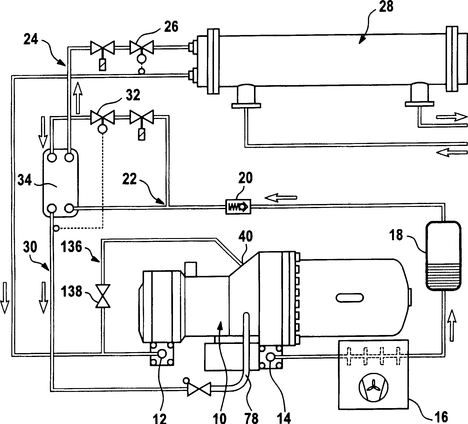
[0049] figure 1 The shown first embodiment of the screw compressor according to the invention comprises a compressor housing generally designated 10 with a suction connection 12 and a pressure connection 14, wherein a refrigerant medium is sucked in at the suction connection 12 and at the pressure connection 14 discharges the compressed refrigerant medium.

[0050] The compressed refrigerant medium discharged at the pressure connection 14 is first conveyed to a condenser 16 and from there into an intermediate store 18 for liquid refrigerant. After the intermediate storage 18, the liquid refrigerant flows through the one-way valve 20 and the branch 22, from the branch to the expansion valve 26 and the evaporator 28 through the cooling cycle line 24, and then returns to the suction from the evaporator 28. interface12.

[0051] In addition, the refrigeration circuit 24 is assigned a recooling circuit 30 which branches off from the cooling circuit 24 on the branch 22 and has an ...


PUM


Abstract

The compressor has two screw rotors arranged in rotor bores in a compressor casing (10), where the rotors compress a refrigerant. A refrigerant inlet in the casing receives the refrigerant from a supercooling circuit (30) and passes it to an inlet in a system of lines. The inlet opens out into compression spaces enclosed by the rotors and the bores. A damper channel precedes the inlet and associated with the system of lines.

Description

technical field [0001] The invention relates to a screw compressor, which comprises two screw rotors arranged in the screw rotor hole in the compressor shell, which compress the refrigerant medium entering from the refrigerant medium inlet and discharge it at the refrigerant medium discharge port, and also include a screw rotor arranged in the compressor shell The inlet inside is used for the refrigerant medium delivered from the recooling circulation line to the inlet through the piping system, wherein the inlet is arranged so that it passes into the compression chamber surrounded by the screw rotor and the screw rotor hole. Background technique [0002] The problem in this type of screw compressor is that since the compression chamber surrounded by the screw rotor and the screw rotor bore moves beside the inlet, pressure vibrations or pulsations are generated, which are transmitted to the piping system of the recooling circuit and cause noise, Stability and sealing issues ...

Claims


Application Information

Patent Timeline
Patent Type & Authority Applications(China)
IPC IPC(8): F04C18/16F04C23/00F04C28/12F04C29/00
CPCF04C28/12F04C23/008F04C29/0035F04C29/0007F04C18/16
Inventor 斯特凡·罗尔克克劳斯·霍斯内尔
Owner BITZER KUEHLMASCHINENBAU GMBH
Features
  • R&D
  • Intellectual Property
  • Life Sciences
  • Materials
  • Tech Scout
  • Unparalleled Data Quality
  • Higher Quality Content
  • 60% Fewer Hallucinations
Learn More