Geashift locking device of automatic speed variator gear lever

A technology of automatic transmission and locking device, which is applied in the direction of transmission control, control device, transportation and packaging, etc. It can solve the problems of troublesome cables for shift lever locks, inconvenient operation, and reduced manufacturing process efficiency.

Inactive Publication Date: 2004-04-28
HYUNDAI MOTOR CO LTD
View PDF0 Cites 31 Cited by
  • Summary
  • Abstract
  • Description
  • Claims
  • Application Information

AI Technical Summary

Problems solved by technology

[0005] Prior art shift lock devices have the disadvantage that it is rather cumbersome and complicated to install the shift lever lock cable for transmitting the control power of the brake pedal to the shift lever lock cam, thereby reducing the efficiency of the manufacturi...

Method used


Image

  • Geashift locking device of automatic speed variator gear lever
  • Geashift locking device of automatic speed variator gear lever
  • Geashift locking device of automatic speed variator gear lever

Examples


Embodiment Construction

[0018] Hereinafter, preferred embodiments of the present invention will be described in detail with reference to the accompanying drawings.

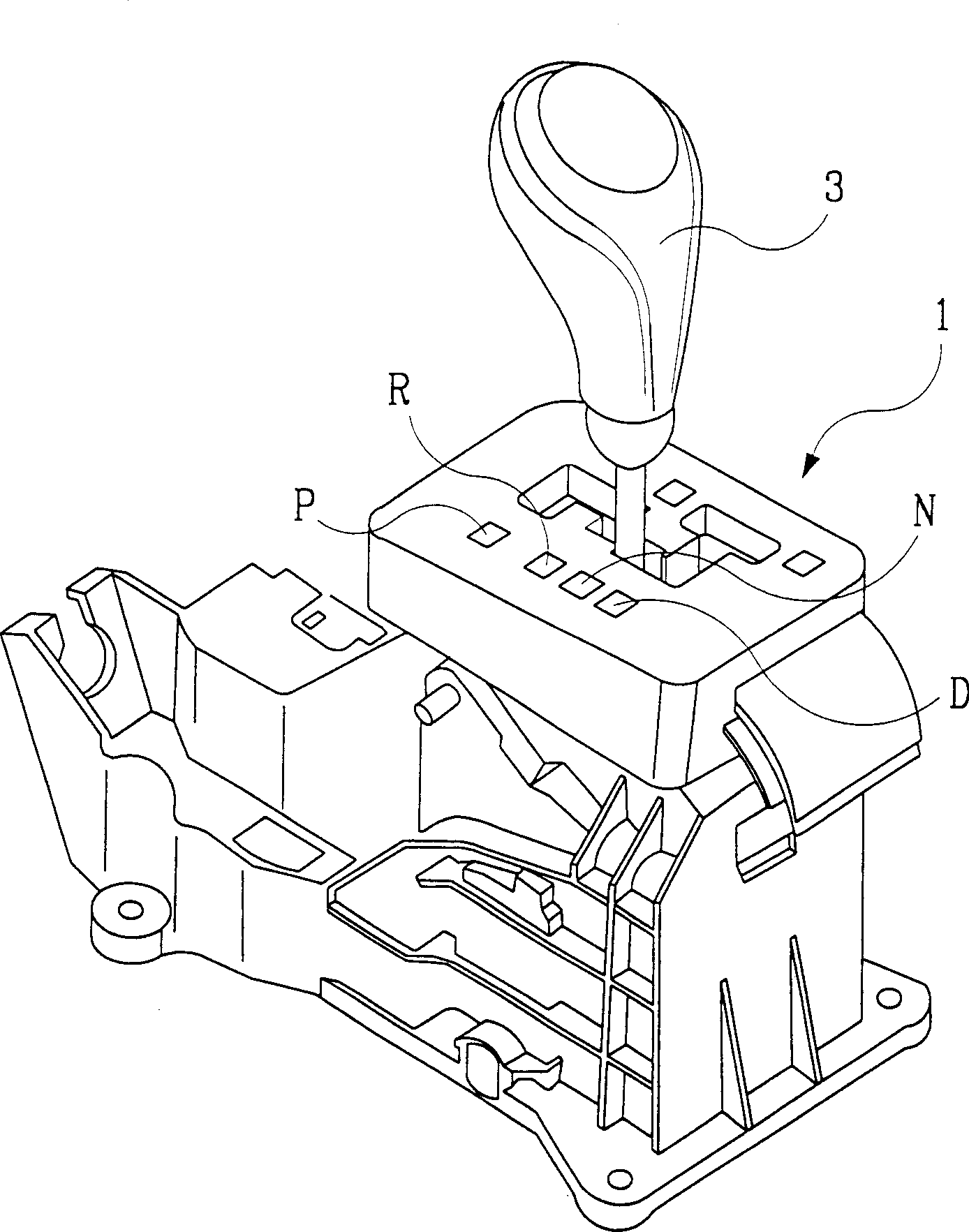
[0019] Paddle shifters for automatic transmissions, such as figure 1 As shown in the middle gear plate bracket 1, set the gears in the order of P, R, N and D. To move the gear lever 3 from the P and N gears to the R gear, the gear lever 3 initially moves laterally from the P and N gears, and then moves linearly in a vertical direction toward the R gear. The gear plate is installed on the right side of the D gear for manual acceleration and deceleration.

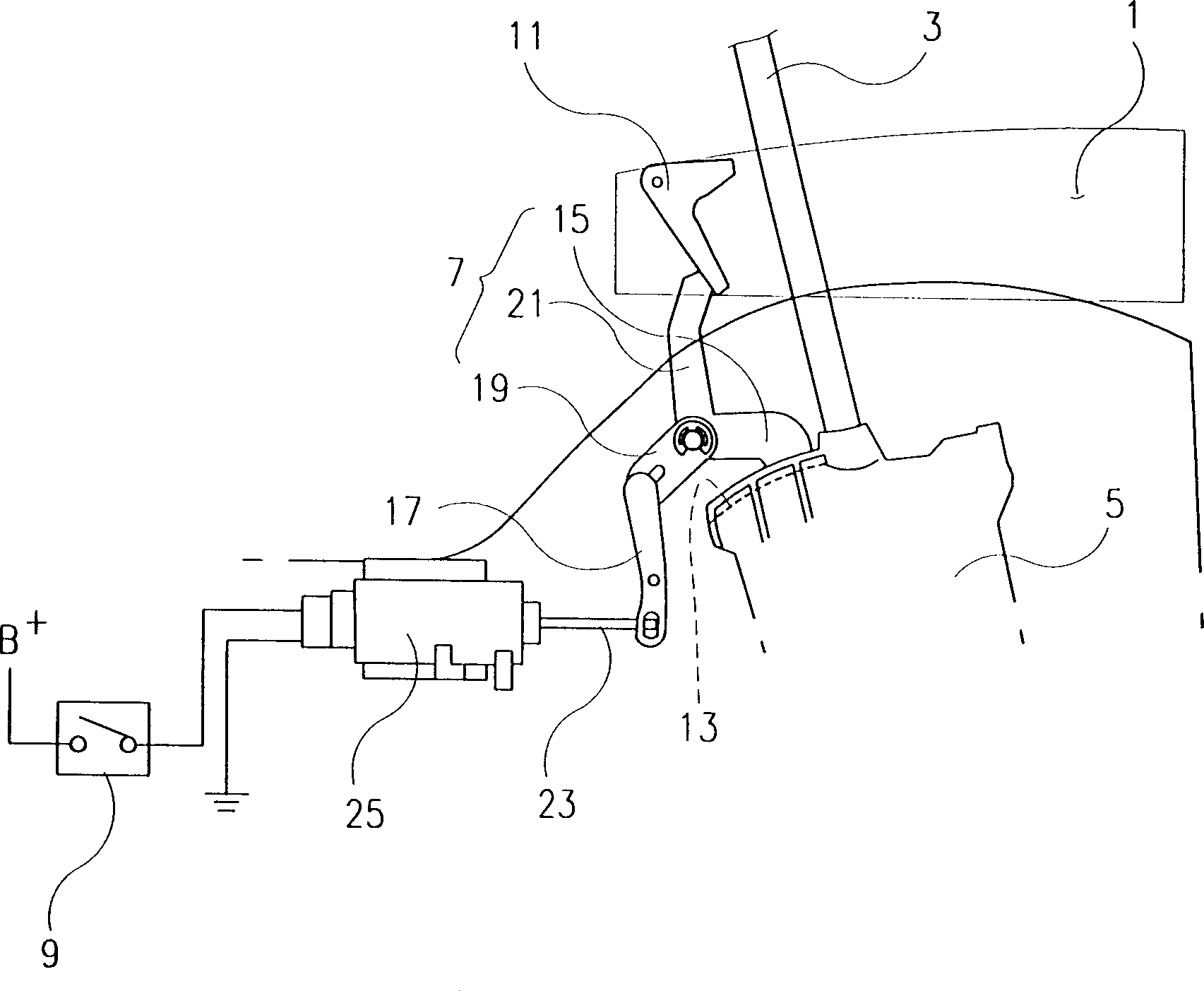
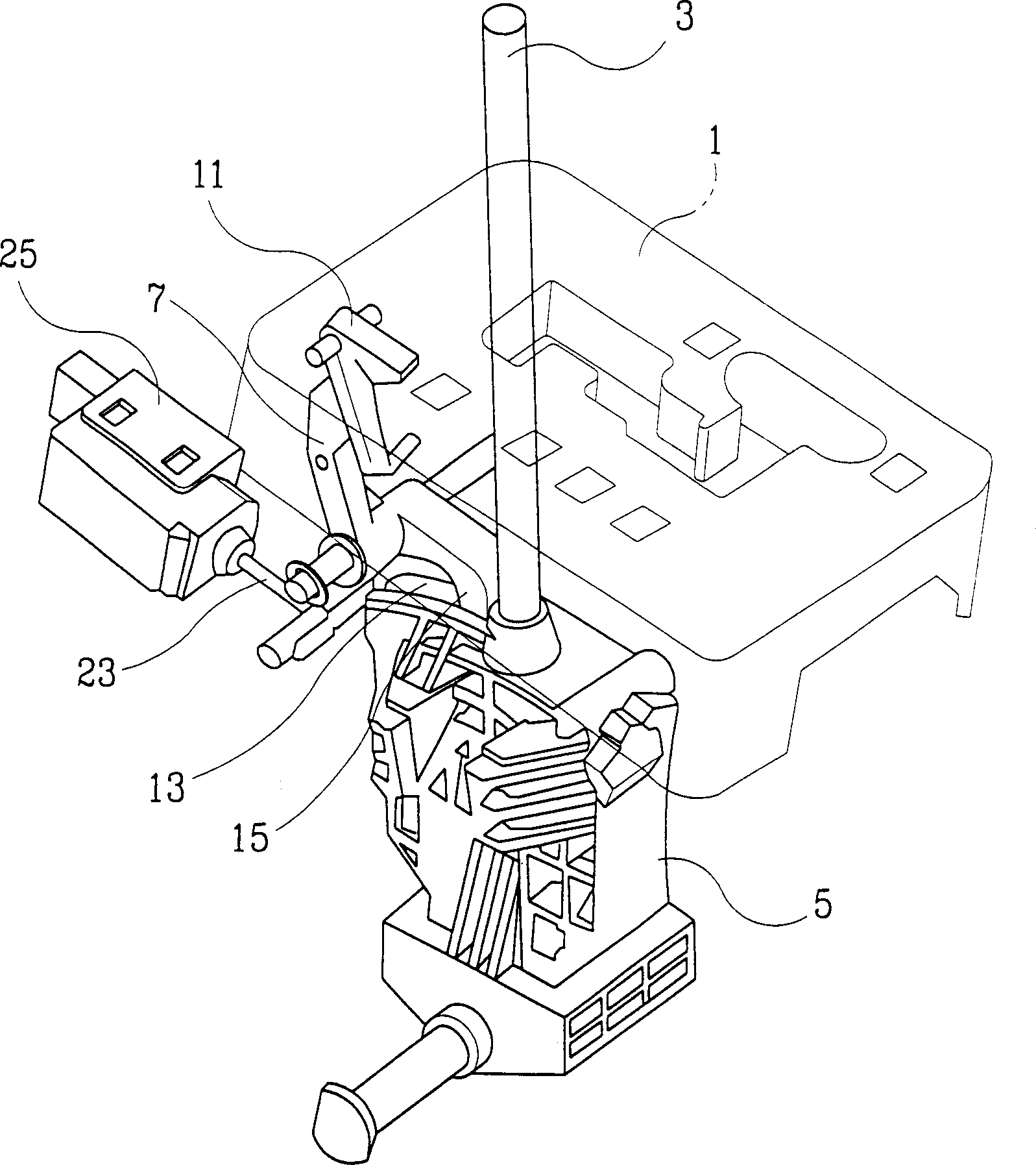
[0020] The preferred embodiment of the present invention structurally includes a cam body 5 integrally mounted to the shift lever 3; a rotating cam 7, which is arranged to act on the cam body 5 to limit the shift lever 3 from moving laterally from the P and N gears; means for driving the rotary cam 7 in response to an electric signal from the brake pedal switch 9; and an emergency lev...


PUM


Abstract

A shift lock device for a shift lever of an automatic transmission, wherein the manipulation or non-manipulation of a brake pedal by a driver is received in the form of an electrical signal to prompt a solenoid actuator to rotate a single rotating cam and to perform a P range shift lock function and a shift lock function from the N range to the R range in a simple structure, such that the conventional cumbersome mounting operation of a shift cable can be eliminated and a simple manipulation of a brake pedal enables a smooth and secured release of the shift lock, thereby improving the convenience of a vehicle.

Description

technical field [0001] The invention relates to a gear shift locking device of a shift lever in an automatic transmission, more specifically, to a shift plate type transmission. Background technique [0002] Usually, the shift lock device is designed to prevent various safety-related accidents. When a novice or a driver who is not used to an automatic transmission vehicle manipulates the shift lever to start the vehicle, the driver suddenly depresses the accelerator pedal without depressing the accelerator pedal. Use when pressing the brake pedal. [0003] The shift lock is engaged when the vehicle is parked to prevent operation of the gear lever. The shift lock is released when the ignition is switched on and when the driver depresses the brake pedal after the car is started and while in motion, thereby enabling the driver to operate the gear lever. [0004] Prior art shift lock devices consist of a shifter lock cable connected to the brake pedal, and a shifter lock cam (...

Claims


Application Information

Patent Timeline
IPC IPC(8): B60K20/02F16H59/10F16H59/54F16H61/22
CPCF16H61/22F16H2061/223F16H59/10F16H59/54B60K20/02
Inventor 赵阳来
Owner HYUNDAI MOTOR CO LTD
Why Eureka
Try Eureka