Crankshaft upsetting left and right die with hidden locking sliding pins

A mold, left and right technology, applied in the direction of manufacturing tools, forging/pressing/hammer devices, forging/pressing/hammering machinery, etc., can solve problems such as hidden safety hazards, eliminate hidden dangers, reduce production costs, and mold replacement efficiency. improved effect

Active Publication Date: 2021-08-20
LIAONING 518 INTERNAL COMBUSTION ENGINE FITTINGS
View PDF6 Cites 0 Cited by
  • Summary
  • Abstract
  • Description
  • Claims
  • Application Information

AI Technical Summary

Problems solved by technology

In this way, during the process of installing and disassembling the mold, especially the process of installing and disassembling the L-shaped long press block, the operator's assembly work range is always within the coverage of the upper, left, and right moving blocks and the mould, which poses a safety hazard

Method used


Image

  • Crankshaft upsetting left and right die with hidden locking sliding pins
  • Crankshaft upsetting left and right die with hidden locking sliding pins
  • Crankshaft upsetting left and right die with hidden locking sliding pins

Examples


Embodiment Construction

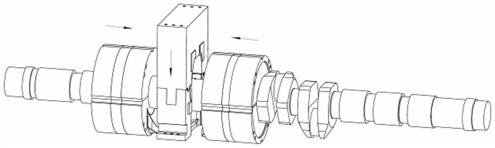
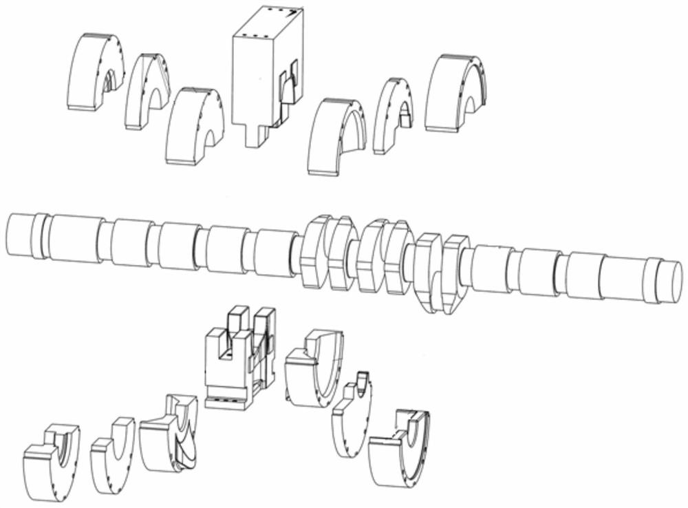
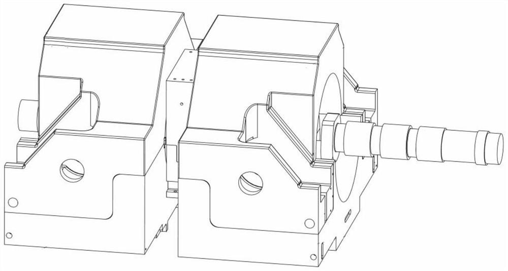
[0039] Such as Figure 6-16 As shown, a left and right mold for upsetting crankshaft with hidden locking sliding pin, including moving block tooling, mold, long hexagon socket head screw 20, backstop pressure block 14, sliding pin 15 and cylinder head hexagon socket head screw 19;

[0040] The moving block tooling is divided into a left upper moving block 1, a right upper moving block 2, a left lower moving block 3 and a right lower moving block 4;

[0041] Described mold is divided into the left side upper die combination mold 5, the right side upper mold combination mold 6, the left side lower mold combination mold 7 and the right side lower mold combination mold 8; Among the side upper mold combination mold 5, the right upper mold combination mold 6, the left lower mold combination mold 7 and the right lower mold combination mold 8, the first piece of mold 9 is close to the side edge of the movable block tooling;

[0042] Design and manufacture the groove a10 formed by the...


PUM


Abstract

The invention relates to a forging die applied to upsetting of a large crankshaft, in particular to a crankshaft upsetting left and right die with hidden locking sliding pins. The die has the characteristic of a semicircular outer contour, a semicircular groove structure with a certain depth and a tangent line of the semicircular groove structure horizontally extending is arranged below the vicinity of a parting surface with the maximum diameter on the two sides, and sliding pin horizontal guide blind holes are formed in the positions, corresponding to an upper left upsetting movable block tool, a lower left upsetting movable block tool, an upper right upsetting movable block tool and a lower right upsetting movable block tool for assembling and installing the die, of the groove. A rectangular groove with two open sides is formed in the tail end of each guide blind hole, a threaded hole is formed in the tail end of each guide blind hole in the length direction, the sliding pins are arranged in the guide blind holes, and after the sliding pins lock the die, sliding pin retaining pressing blocks are connected and assembled in the rectangular grooves through screws, so that sliding rods do not retreat at the mold locking positions, and the sliding pins are hidden and protected. The crankshaft upsetting left and right die has the advantages of high assembling and disassembling efficiency and good replacing and operating safety of the left and right upsetting dies, and meanwhile, the manufacturing cost of the left and right dies adopting other locking structure modes is reduced.

Description

technical field [0001] The invention belongs to the technical field of crankshaft upsetting and forging production technology, and in particular relates to a left and right mold for upsetting crankshaft with hidden locking sliding pins. Background technique [0002] Crankshaft upsetting and forging production technology is a production method in which each crankshaft is independently molded, locally heated, and locally subjected to upsetting and forging. Each batch of forgings needs to be centralized and unified to change the mold, local heating, and local upsetting to produce the same crank, and then centrally and uniformly change the mold, local heating, and local upsetting to the next same crank. After mold, local heating, and local upsetting, the forging production of the batch of forgings of each crank throw and flange of the large crankshaft is completed. [0003] For the forging billet in the general forging production process, the design outline of each crank throw ...

Claims


Application Information

Patent Timeline
Patent Type & Authority Applications(China)
IPC IPC(8): B21J13/02
CPCB21J13/025
Inventor 邓军疆张晓宇
Owner LIAONING 518 INTERNAL COMBUSTION ENGINE FITTINGS
Why Eureka
Try Eureka