Phase locked loop for controlling recordable optical disk drive

A phase-locked loop, control voltage technology, applied in data recording, recording signal processing, recording information storage, etc., can solve the problems of inability to synchronize data blocks, increased cost and complexity of optical disc drives, etc.

Inactive Publication Date: 2004-06-02
MEDIATEK INC
View PDF1 Cites 6 Cited by
  • Summary
  • Abstract
  • Description
  • Claims
  • Application Information

AI Technical Summary

Problems solved by technology

Using a codec means that the CD-ROM requires additional hardware, thus increasing the cost and complexity of the CD-ROM
Another problem with the prior art proposed by Kuroda et al. is that it is impossible to synchronize the data blocks written to the disc after the address information has been detected by the pre-groove until the next pre-groove is detected.

Method used


Image

  • Phase locked loop for controlling recordable optical disk drive
  • Phase locked loop for controlling recordable optical disk drive
  • Phase locked loop for controlling recordable optical disk drive

Examples


Embodiment Construction

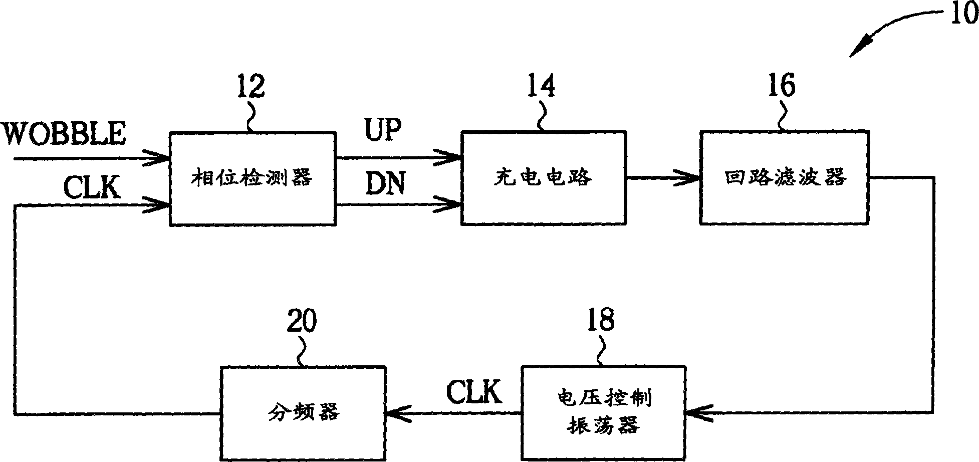
[0044] see Figure 6 , Figure 6is a block diagram of a phase-locked loop 100 according to the present invention. The phase detector 12 , the charging circuit 14 , the loop filter 16 , and the voltage-controlled oscillator (VCO) 18 of the prior art PLL 10 are all used in the PLL 100 of the present invention. The operation of each element is the same as that of the prior art, and will not be repeated here. In addition to the above components, the PLL 100 also includes a first frequency divider 106 , a second frequency divider 102 , a phase shift detection circuit 104 , and a phase adjustment circuit 108 .

[0045] After receiving the control voltage from the loop filter 16, the voltage controlled oscillator 18 generates the clock signal CLK. The clock signal is then input to the first frequency divider 106 and the second frequency divider 102 . The first frequency divider divides the clock signal CLK into a group of multi-phase signals CLK_MULTI, and the second frequency di...


PUM


Abstract

The invention provides a phase locked loop (PLL) for producing oscillation signal, wherein the oscillation signal can sustain stabilized phase difference relative to the reference signal. The phase locked loop includes a first frequency divider, a phase shift detection circuit and a phase-adjusting circuit.

Description

technical field [0001] The present invention relates to a phase locked loop (PLL), in particular to a recordable optical disk drive using the phase locked loop. When recording data to a recordable optical disk, a phase shift detection operation is performed. Background technique [0002] A phase-locked loop is used for frequency control. see figure 1 , figure 1 It is a block diagram of a known phase-locked loop 10 for controlling a recordable optical disc player. The PLL 10 responds to the wobble signal (WOBBLE) and generates a clock signal (CLK). Such as figure 2 As shown, the wobble signal is obtained from a wobble track on a recordable optical disc, and contains address information of the wobble track. The clock signal is used to control the writing path of the recordable optical disc drive, and serves as a reference for the recording clock. For the DVD-R / RW specification, one wobble signal period is equivalent to 186 recording clock signal periods, and for the DVD...

Claims


Application Information

Patent Timeline
Patent Type & Authority Applications(China)
IPC IPC(8): G11B7/007G11B20/10
CPCG11B20/10212G11B20/10425G11B20/10222G11B7/24082
Inventor 徐哲祥陈宏庆
Owner MEDIATEK INC
Why Eureka
Try Eureka