Microscope for operation

A technology for surgery and microscopes, applied in the direction of surgical microscopes, microscopes, surgery, etc.

Inactive Publication Date: 2004-08-11
KK TOPCON
View PDF2 Cites 3 Cited by
  • Summary
  • Abstract
  • Description
  • Claims
  • Application Information

AI Technical Summary

Problems solved by technology

[0004] However, in the above-mentioned surgical microscope system, when the surgical microscope is not use

Method used


Image

  • Microscope for operation
  • Microscope for operation
  • Microscope for operation

Examples


Embodiment approach 1

[0030] [constitute]

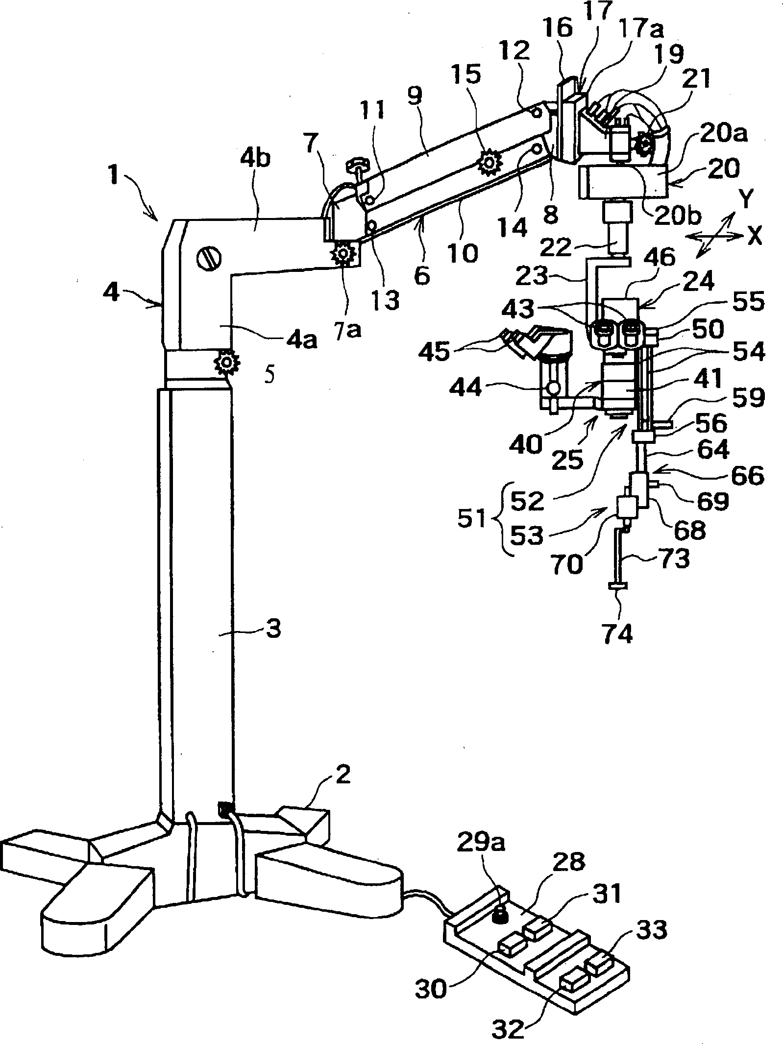
[0031] exist figure 1 Among them, 1 is a microscope device for surgery, 2 is a support base of the microscope device 1 for surgery, 3 is a pillar integrally provided with the support base 2 facing up and down, and 4 is a first arm mounted on the upper end of the pillar 3. .

[0032] The first arm 4 is formed by a support part 4a rotatably attached to the upper end of the support column 3 around a vertical rotation axis (vertical axis), and an arm part 4b provided continuously with the support part 4a horizontally. word shape. 5 is a fixing screw for fixing the supporting part 4a to the upper end part of the pillar 3.

[0033] In addition, 6 is the second arm (swing arm) of the parallel link type. The second arm 6 has a first support member 7, a second support member 8, and a pair of connecting rods 9, 10. The first support member 7 is horizontally rotatably mounted on the second arm through a rotating shaft (not shown) extending up and down. On the f...

Deformed example 1

[0116] In the embodiment described above, if the operation signal from the upward coarse motion switch 30 is input to the calculation control circuit 27, the first drive motor 18 of the first electric up and down movement device 17 is controlled to make the supporting part 19 relatively At the second arm 6, the upward micromotion is performed at the speed v1, and at the same time, the second drive motor 26 of the second electric vertical movement device 24 is controlled to make the surgical microscope 25 slightly upward at the speed v2 relative to the supporting frame 23. As a result, the surgical microscope 25 is moved upward and coarsely at the speed (v1+v2) relative to the second arm 6. However, it is not limited to this configuration.

[0117] That is, when the operation signal from the ascending coarse switch 30 is input, the supporting part 19 moves at a speed V (V>>v1) relative to the second arm 6 through the first electric up and down movement device 17 through the cal...


PUM


Abstract

An operation microscope apparatus includes: an operation microscope (25) supported to a pillar through an electrically-operated elevating device for rough-motion (first upward-and-downward micro motion device 17) ; a lens support arm (51) supported to a support portion of the operation microscope (25) so as to be movable between a use position at which the lens support arm (51) is extended downward and a storage position at which the lens support arm (51) is stored upward; a front lens (74) held by the lens supported arm (51); a control unit for controlling the electrically-operated elevating device (arithmetic and control circuit 27) ; a switch for upward-and-downward rough-motion (30,31 or 94,95); and a detection unit for detecting a storage state of the lens support arm (51) to output a detection signal (microswitch 91). In the apparatus, only when the detection signal is received, the control unit (arithmetic and control circuit 27) controls the electrically-operated elevating device (first electrical upward-and-downward micro motion device 17) by operating the switch (30,31 or 94,95) to allow the operation microscope (25) to roughly move upward and downward.

Description

technical field [0001] The invention relates to a microscope device for surgery. The microscope device for surgery is provided with a front lens which can be arranged in front of the objective lens of the microscope for surgery. Supported on the microscope support. Background technique [0002] Known as a conventional surgical microscope system is a swing microscope in which the first arm is mounted on the upper end of the support in a horizontally rotatable manner, and at the same time, the free end of the first arm is horizontally rotatable and One end of the second arm (microscope support portion) can be oscillated up and down, and a surgical microscope is installed on the other end of the second arm by an electric up and down fine movement device (for example, refer to JP-A-6-22980). [0003] In addition, known as this surgical microscope, by arranging a front lens in front of the objective lens of the observation optical system, the eye to be inspected is observed thro...

Claims


Application Information

Patent Timeline
IPC IPC(8): G02B21/24A61B3/13A61B19/00G02B7/00
CPCG02B7/001A61B19/5223A61B3/13A61B19/26A61B90/50A61B90/20C08J7/04C09D5/22
Inventor 秋山宏高木和俊
Owner KK TOPCON
Why Eureka
Try Eureka