
Operating microscope

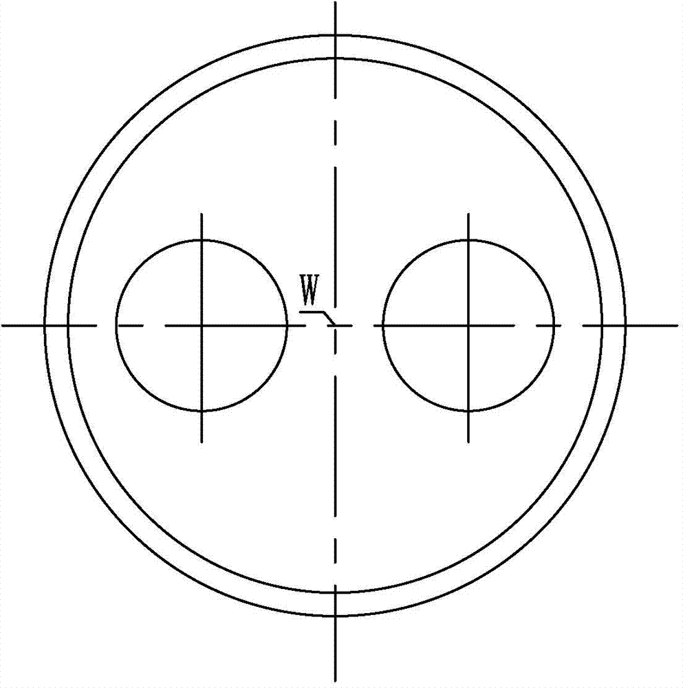
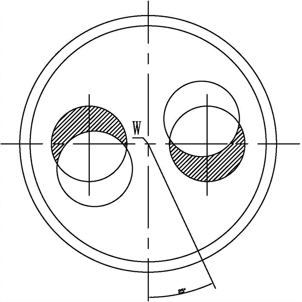
A surgical microscope and mirror body technology, applied in the field of surgical microscopes, can solve the problems of binocular field of view edge occlusion and incomplete observation, and achieve the effect of compact structure and clear imaging

Active Publication Date: 2015-06-24
ZUMAX MEDICAL
View PDF5 Cites 2 Cited by
  • Summary
  • Abstract
  • Description
  • Claims
  • Application Information

AI Technical Summary

Problems solved by technology

However, during the swing observation of the operating microscope, it was found that the edge of the binocular field of view was obviously blocked after the swing, resulting in incomplete observation

Method used


Image

  • Operating microscope
  • Operating microscope
  • Operating microscope

Examples


Embodiment approach 1

[0032] Implementation mode one: if Figure 5 , 6 Shown: it is a Galileo telescope group, and the Galileo telescope group of the first relay lens group 11 is reversely set. Specifically: the first transfer lens group 11 of the Galileo telescope group is arranged in reverse and includes a negative lens group 11a and a positive lens group 11b arranged in sequence, while the second transfer lens group 13 of the Galileo telescope group is arranged in a forward direction. Positive lens group 13a, negative lens group 13b.

[0033] The structural parameters of the Galileo telescope group of the first image transfer lens group 11 and the second image transfer lens group 13 can be the same: as the negative lens group and the positive lens group are all made of doublet lenses, the image side focal point and the positive lens group of its negative lens group 11a The focus of the object side of the lens group 11b overlaps, and the focus of the image side of the positive lens group 1...

Embodiment approach 2

[0041] Implementation mode two: if Figure 7 Shown: it is the Capra telescope group, and the Capra telescope group of the first transfer lens group 11 is also set in reverse. Specifically: the first image transfer lens group 11 and the second image transfer lens group 13 are two-piece positive lens groups, wherein the first image transfer lens group 11 is sequentially provided with positive lens groups 11c, 11d, and the second image transfer lens group 13 Set positive lens groups 13c, 13d in sequence, wherein the positive lens groups 11c and 13d are the same, and the positive lens groups 11d and 13c are the same.

[0042] In this example, the positive lens groups are all made of doublet lenses, the image focus of the positive lens group 11c coincides with the object focus of the positive lens group 11d, and the image focus of the positive lens group 13c coincides with the object focus of the positive lens group 13d.


PUM


Abstract

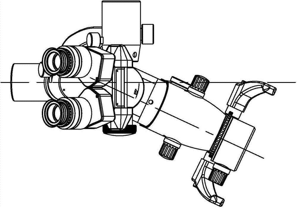
The invention relates to an operating microscope. The operating microscope comprises a main microscope body and a binocular lens barrel seat, wherein the main microscope body can swing towards two sides of the binocular optical axis in the plane perpendicular to the binocular optical axis of the binocular lens barrel seat with respect to the binocular optical axis, and a large objective lens group and a zoom group are arranged in the main microscope body along the first optical axis. A small objective lens group and an eye lens group are arranged in the binocular lens barrel seat. The operating microscope further comprises an image deflecting and inverting system, wherein the image deflecting and inverting system comprises a first image inverting lens group for expanding imaging ray beams, an image inverting prism for converting an imaging light angle and a second inverting lens group for gathering imaging ray beams, the first image inverting lens group and the image inverting prism are fixed in the main microscope body along the first optical axis, the second inverting lens group is fixed in the binocular lens barrel seat, and imaging rays are observed along the large objective lens group, the zoom group, the first image inverting lens group, the image inverting prism, the second inverting lens group, the small objective lens group and the eye lens group. The operating microscope is compact in structure and clear and complete in imaging.

Description

technical field [0001] The invention relates to the field of medical optical instruments, in particular to an operating microscope. Background technique [0002] In recent years, a kind of operating microscope with yaw observation function has appeared, referring to the U.S. patent whose publication number is US6982827, which discloses a kind of operating microscope with yaw device, and this yaw device can make the doctor keep his head while observing. When the central position is fixed, the main mirror body swings in a plane perpendicular to the binocular visual axis to change the observation direction, such as Figure 1a , 1b shown. However, when the operating microscope was oscillating for observation, it was found that the edge of the binocular field of view was obviously blocked after the oscillating, resulting in incomplete observation. Contents of the invention [0003] The object of the present invention is to provide an operating microscope. [0004] I...

Claims


Application Information

Patent Timeline
Patent Type & Authority Applications(China)
IPC IPC(8): G02B21/22G02B21/24
CPCG02B21/22G02B21/248
Inventor 李剑月周晓峰王吉龙
Owner ZUMAX MEDICAL
Learn More