Folder binding clips

A technology for binders and folders, applied in folders, printing, etc., can solve the problems of impairing installation workability, unable to maintain stable installation state, unstable contact state, etc.

Inactive Publication Date: 2004-09-01
KOKUYO CO LTD
View PDF1 Cites 1 Cited by
  • Summary
  • Abstract
  • Description
  • Claims
  • Application Information

AI Technical Summary

Problems solved by technology

In this way, since the front end of the stopper contacts the curved surface of the binder main body in a state almost in line contact, the contact state is unstable, resulting in a problem that a stable mounting state cannot be maintained.
[0006] In addition, since the aforementioned stopper is a member in which a small piece formed by cutting three sides in a substantially U-shape remains in a state where one end is connected to the fixing member, a certain amount of elasticity is applied to the aforementioned one end, and it is fixed from below. Press processing, cutting and erecting a member that is approximately linear from a side view (refer to FIG. 14 of the aforementioned patent document), so it is difficult to align the front end of the stopper with the staple when the cutting and erecting is insufficient. The curved portion of the clip body reliably contacts the
Therefore, in order to make the front end of the stopper come into reliable contact with the bent portion of the binder body, it is considered to use a form of pushing up the stopper with a suitable tool from the outer side of the folder cover, but this leads to problems during installation. Other tools must be used, causing problems that impair installation workability

Method used


Image

  • Folder binding clips
  • Folder binding clips
  • Folder binding clips

Examples


Embodiment Construction

[0038] Hereinafter, one embodiment of the present invention will be described with reference to the drawings.

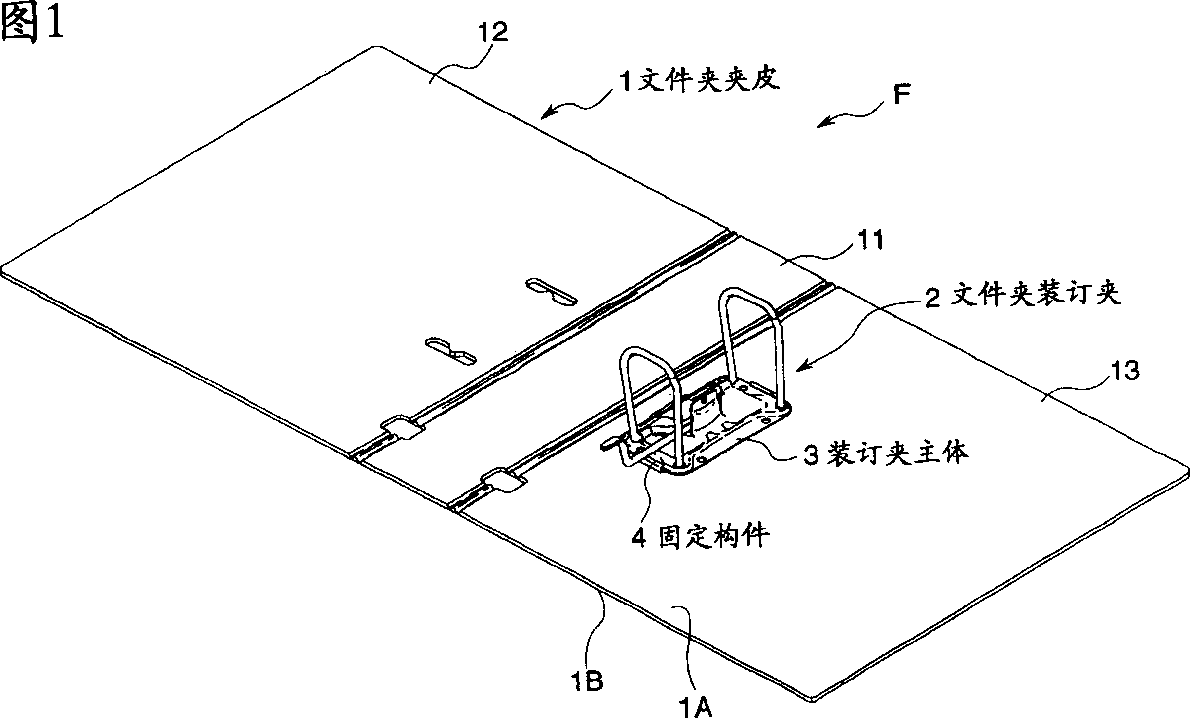
[0039] The file binder 2 according to the present embodiment is applicable to, for example, the file folder F shown in FIG. 1 . The folder F is composed of a folder cover 1 and a folder binder 2 integrally attached to the folder cover 1 .

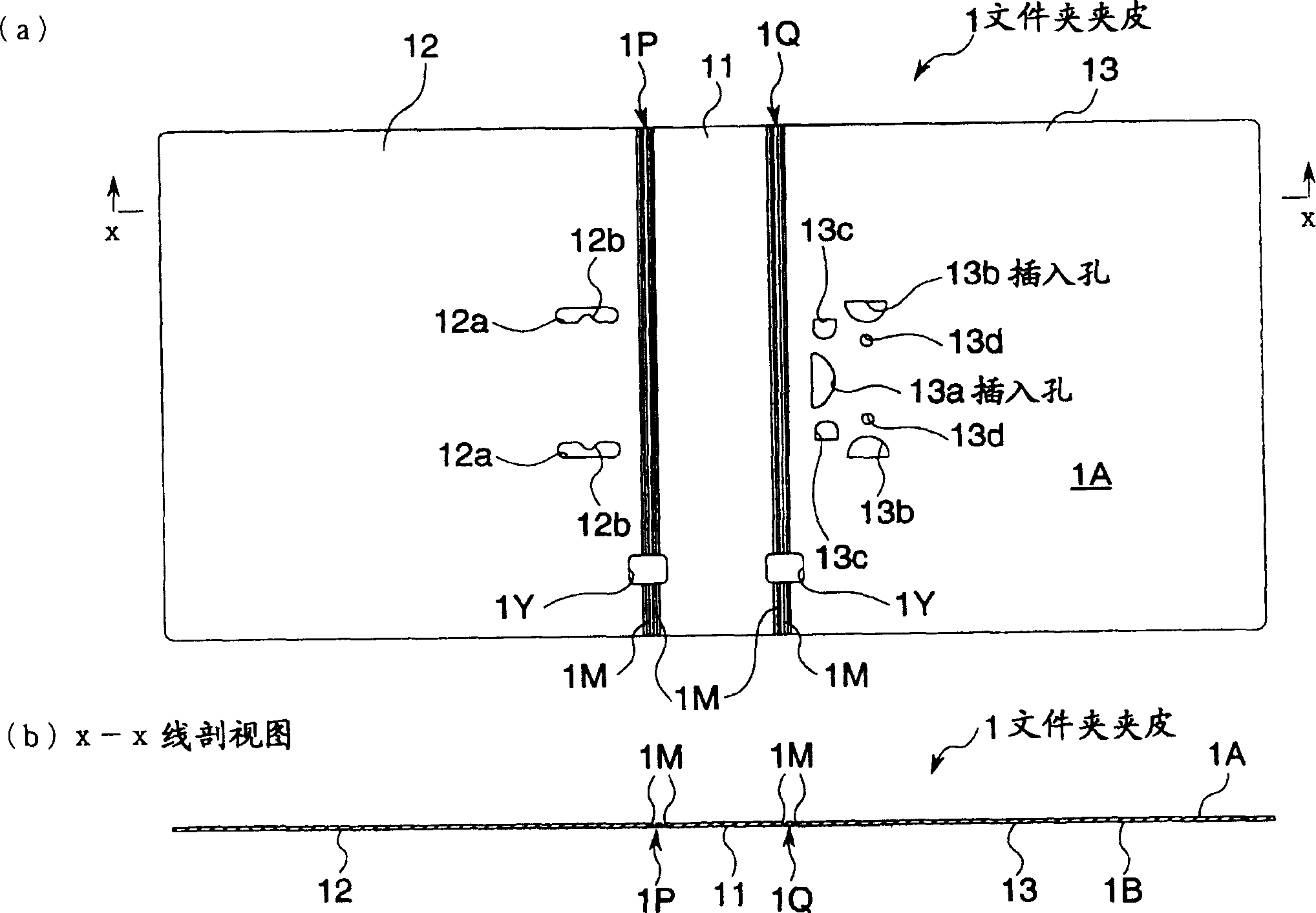
[0040] Such as figure 2 (a), the front view in the unfolded state, and figure 2As shown in the sectional view along the x-x line in (a) in (b), the folder cover 1 is an integral molded part made of, for example, a synthetic resin material, which includes: a clip back 11, and a pair of clamp backs 11 The jacket surface 12 and the jacket bottom 13 are provided. The structure of the folder cover 1 is that a groove portion 1M with a hinge function is set on the interface portion 1P between the folder back 11 and the cover surface 12, and the interface portion 1Q between the folder back 11 and the cover bottom 13, and the hinge func...


PUM


Abstract

This file binder comprises the file binder body 3 to be fitted to an inner surface 1A side of a file surface 1 by pinching the file surface 1 between them, and the fixing component 4 for freely detachably fixing the file binder body 3 by sliding-transfer by being fitted to an outer surface 1B side. A first control part 42 and a second control part 43 for restricting the transfer in a slide fitting direction of the file binder body 3 and a transfer in a direction almost crossing at an almost right angle the slide fitting direction by inserting the fixing component 4 into inserting holes 13a, 13b of the file surface from the outer surface 1B side of the file surface 1 to be projected out to the inner surface 1A side, are provided. A stopper 44 having an abutting surface 44b raised in a posture forming an almost right angle to the slide fitting direction is provided to the fixing component 4. By making an opening edge part 31b1 facing a slide detaching direction of an opening part 31b formed to the file binder body 3 abut against the abutting surface 44b, slide transfer in the slide detaching direction of the file binder body 3 positioning at a specific fitting position is resitricted.

Description

technical field [0001] The invention relates to a folder binder suitable for file folders. Background technique [0002] In recent years, in view of the need for waste classification and recycling, it is desired to have a folder binder that can be simply separated from the folder cover when discarded. As an example, there is known a method in which, for example, a binder main body mounted on the inner side of a folder folder is slidably moved and detachably fixed to a fixing member on the outer side of the folder folder. This type of folder binder is provided on the fixing member to restrict the movement toward the sliding installation direction of the binder main body (the direction in which the binder main body is installed to a predetermined installation position) and the direction approximately perpendicular to the sliding installation direction. The restricting part of the movement, and a part of the fixing member have a certain angle with respect to the sliding instal...

Claims


Application Information

Patent Timeline
Patent Type & Authority Applications(China)
IPC IPC(8): B42F13/00B42F13/22
Inventor 清见多喜夫辻野伸明
Owner KOKUYO CO LTD
Why Eureka
Try Eureka