Light source device and projecton type display deivce using the light source device

A light source device and light emission technology, applied in projection devices, optics, light guides, etc., can solve the problems of high cost dichroic prism 201, image display quality degradation, uneven color, etc.

Inactive Publication Date: 2004-10-20
VICTOR CO OF JAPAN LTD
View PDF1 Cites 17 Cited by
  • Summary
  • Abstract
  • Description
  • Claims
  • Application Information

AI Technical Summary

Problems solved by technology

[0019] That is, the first problem is that, corresponding to the LED arrays 203R, 203G, and 203B of R, G, and B colors, each R, G, and B needs a lens array 204R, 204G, and 204B, and a two-way LED array with high cost is required. Prism 201, so it is difficult to realize cost reduction and miniaturization of projection display device and light source device
[0020] In addition, the second problem is that due to the light emission differences among the LEDs in the LED arrays 203R, 203G, and 203B of the R, G, and B colors, the light emission brightness is not necessarily the same in the plane. When , B are different, when displaying white light, the color will be uneven, which will significantly reduce the image display quality

Method used


Image

  • Light source device and projecton type display deivce using the light source device
  • Light source device and projecton type display deivce using the light source device
  • Light source device and projecton type display deivce using the light source device

Examples


no. 1 example

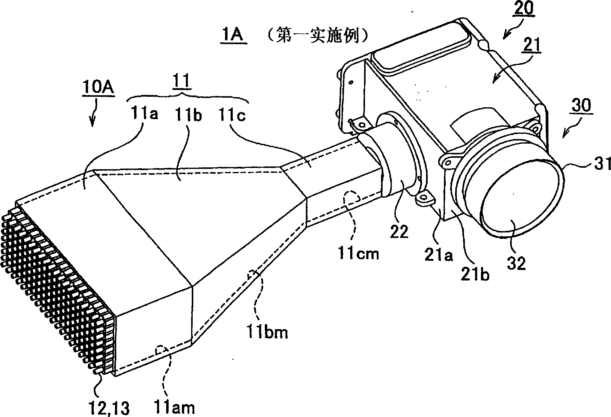
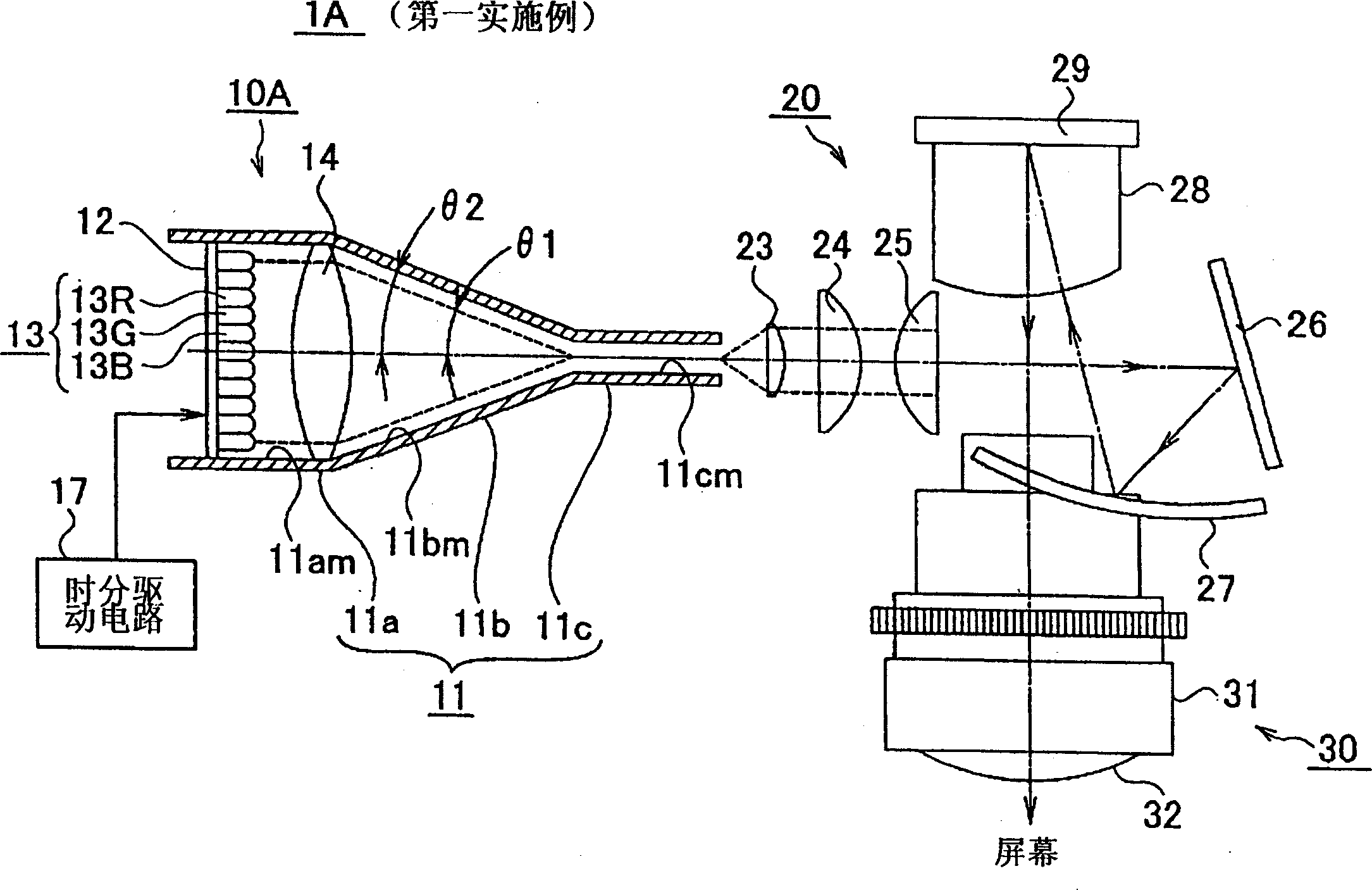
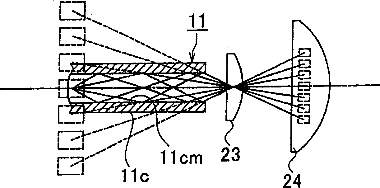
[0052] figure 1 It is an external view showing the light source device of the first embodiment of the present invention and the projection display device of the first embodiment using the light source device, figure 2 is a configuration diagram showing a light source device according to a first embodiment of the present invention and a projection display device according to a first embodiment using the light source device, image 3 In the light source device of the first embodiment of the present invention, the reflection mirror surface formed in the small square column part of the light guide repeatedly reflects the state of each color light from the LED array, Figure 4 It is a figure which shows the red LED, green LED, and blue LED which comprise the LED array in the light source apparatus of the 1st Embodiment of this invention, (a) is a top view, (b) is a front view, (c) is a bottom view, (d) is a side view, (e) is a perspective view, Figure 5 It is a figure showing t...

no. 2 example

[0072] Figure 7 It is a configuration diagram showing a light source device according to a second embodiment of the present invention and a projection display device according to a second embodiment using the light source device.

[0073] Figure 7 The shown light source device 10B of the second embodiment of the present invention and the projection display device 1B of the second embodiment using the light source device 10B are identical to the light source device 10A of the first embodiment and the first embodiment described above except for a part. The projection display device 1A of one embodiment has the same configuration, and for the convenience of description, the same reference numerals are used for the same components as those of the first embodiment, and new components are used for the components different from those of the first embodiment. , and only the differences from the first embodiment will be described.

[0074] That is, if Figure 7 As shown, the proje...

no. 3 example

[0080] Figure 8 It is a structural view showing a light source device according to a third embodiment of the present invention and a projection display device using the light source device according to a third embodiment. FIG. 9 is an exploded perspective view showing the light source device according to a third embodiment of the present invention, Figure 10 It is a partially cutaway perspective view of the light source device according to the third embodiment of the present invention. FIG. 11(a) is used to illustrate the LED lens array, ring Perspective views of various aspect ratios of the lens, light guide, and DMD.

[0081] Figure 8The shown light source device 10C of the third embodiment of the present invention and the projection display device 1C of the third embodiment using the light source device 10C are identical to the light source devices of the first and second embodiments described above except for a part. 10A, 10B have the same configuration as the project...


PUM


Abstract

A light emitted from a semiconductor light emitting device array having a plurality of semiconductor light emitting devices arranged two-dimensionally on a substrate is converged by a condensing lens. In a light guide, a mirror surface is formed from a light incidence port to a light emission port along an inner wall surface. The semiconductor light emitting device array and the condensing lens are arranged in that order toward the light emission port inside the light incidence port of the light guide. A part of the inner wall surface of the light guide is narrowed down substantially along a condensing angle of the condensing lens. The light guide includes parallel inner wall surfaces facing each other, following a portion obtained by narrowing down a part of the inner wall surface, in order to emit the light (each color light) converged by the condensing lens while repeatedly reflecting the light on the mirror surface.

Description

technical field [0001] The present invention relates to a light source device capable of ensuring in-plane luminance uniformity of light emitted from a semiconductor light emitting element array, and a projection display device using the light source device. Background technique [0002] Recently, projection-type display devices for displaying high-definition color images representative of the high-definition television broadcasting standard and the UXGA (Ultra extended Graphics Array) standard for computer graphics have been widely used on a large screen. . [0003] As an image display device for displaying a color image, the above-mentioned projection display device includes a device using a transmissive or reflective spatial light modulation element (such as a liquid crystal panel), or a device using a DMD (Digital Micromirror Device: digital micromirror device). Devices, according to the number of image display devices used in the projection display device, there are si...

Claims


Application Information

Patent Timeline
Patent Type & Authority Applications(China)
IPC IPC(8): G02B6/00G03B21/20H01L33/56H01L33/58H01L33/60
CPCG03B21/2033G03B21/2013G03B21/2066Y10S385/901G03B21/20
Inventor 面田学宫本律
Owner VICTOR CO OF JAPAN LTD
Why Eureka
Try Eureka