Flow equalization device used in pipeline

A technology of pipes and equalizing holes, which is applied in the direction of pipe components, fluid flow, pipes/pipe joints/fittings, etc., which can solve the problems of large water head loss, avoid or reduce vortices, and reduce the pressure loss of water body delivery.

Inactive Publication Date: 2020-09-22
WENZHOU QIANHAN ENERGY SAVING TECH CO LTD
View PDF0 Cites 0 Cited by
  • Summary
  • Abstract
  • Description
  • Claims
  • Application Information

AI Technical Summary

Problems solved by technology

[0003] The purpose of the present invention is to provide a flow equalizing device used in pipelines, which solves the problem of excessive head loss during confluence in the process of drawing water from existing multi-pipes, effectively ensures fluid flow velocity, and reduces turbulent flow in the process of fluid flow

Method used


Image

  • Flow equalization device used in pipeline
  • Flow equalization device used in pipeline
  • Flow equalization device used in pipeline

Examples


Embodiment 1

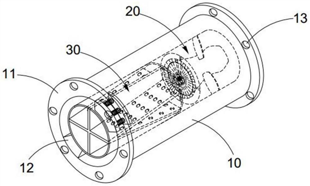
[0030] see Figure 2-7As shown, the flow equalization device used in the pipeline includes:

[0031] The first pipe body 10 is coaxially connected with the second pipe body 31 inside the first pipe body 10 . The water inlet end of the second pipe body 31 is provided with a first flow equalization assembly 30 , and the water outlet end is provided with a second flow equalization assembly 20 .

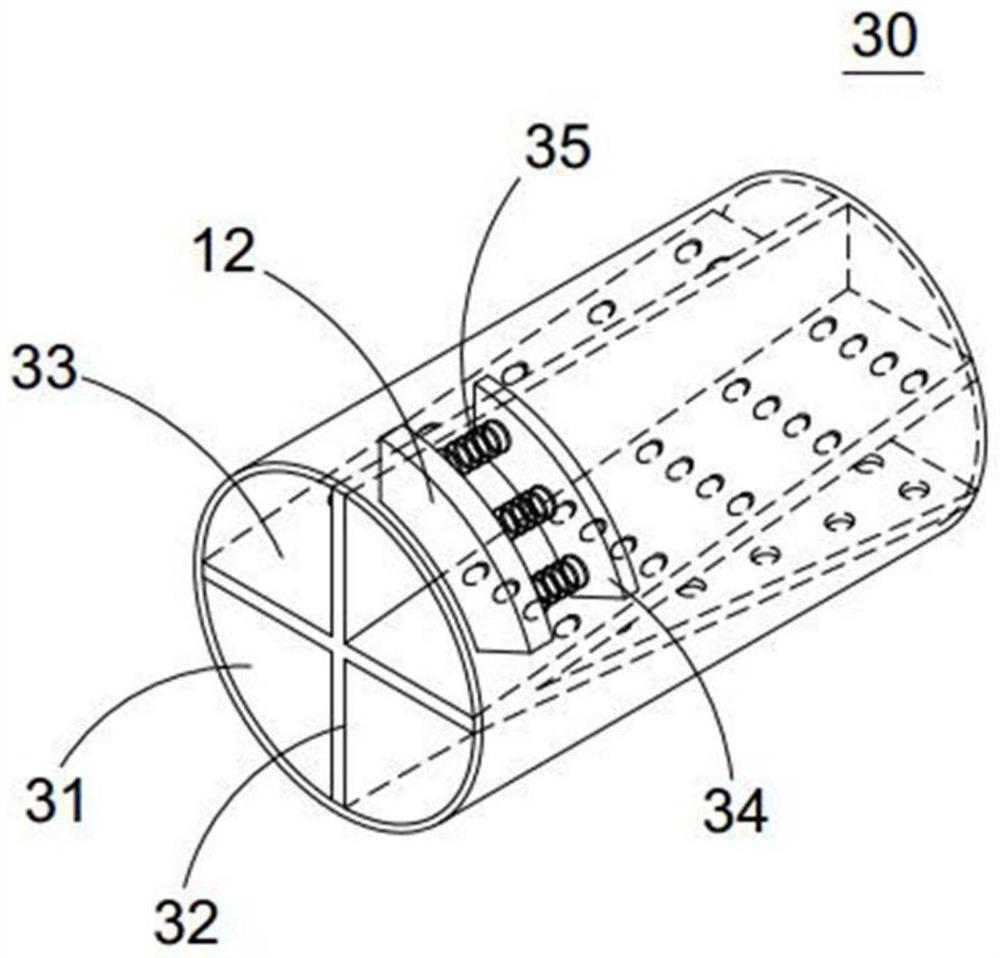
[0032] The inner walls at both ends of the first pipe body 10 are provided with a first connecting plate 12, and the two ends of the second pipe body 12 are provided with a second connecting plate 34 corresponding to the position of the first connecting plate 12, and the first connecting plate 12 is connected to the second connecting plate 12. The plates 34 are connected by elastic members 35;

[0033] Wherein, the first flow equalizing assembly 30 includes a first splitter plate 32 and a second splitter plate 33 arranged vertically in the second pipe body 31, the second splitter plate ...

Embodiment 2

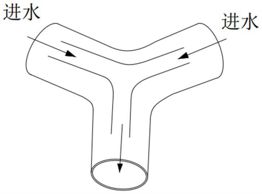
[0044] When the device of the present invention is actually used, it is installed on the water outlet end of the multi-way pipe, specifically connected by a flange, and the necessary sealing treatment is performed to prevent the leakage of the conveying liquid, and the multi-way pipe body pumps the water body under the action of the pump body Entering the main pipe, the device of the present invention performs flow equalization treatment through the device of the present invention during the multi-way pipe multi-stream fluid entering the main pipe. The multi-stream fluid first passes through the first flow equalization assembly 30, and most of the fluid entering the first pipe body 10 is in the second Flowing in the pipe body 31, a small part of the fluid flows from the inner wall of the first pipe body 10 and the outer wall of the second pipe body 31 to realize the stratified flow of the fluid. The distance between the water inlet of the second pipe body 31 and the water inlet...

Embodiment 3

[0046] The first flow equalization assembly 30 and the second flow equalization assembly 20 of the present invention are preferably installed in the same second pipe body 31, and can be installed in different sections of the second pipe body 31 when considering that the transmission path is too large; The elastic member 35 is preferably a rubber spring, which can effectively avoid the problem of metal spring corrosion and pollution of the transmission medium during long-term contact with water bodies. The second pipe body 31 is preferably a metal pipe fitting, but it needs to be sprayed with anti-corrosion and anti-fouling coatings on its inner and outer surfaces. Of course Rubber pipe fittings can also be used as the second pipe body 31. The thickness of the second pipe body 31 is not easy to be too large, and is generally controlled within 0.5-1.5 cm. In addition, the surface of the rotating part 24 can be provided with a guide vane 25 to improve the limit position. Fluid flo...


PUM


Abstract

The invention discloses a flow equalization device used in a pipeline, and belongs to the technical field of pipeline equipment. The flow equalization device comprises a first pipe body, the interiorof the first pipe body is coaxially connected with a second pipe body, the water inlet end in the second pipe body is provided with a first flow equalization assembly, and the outlet end of the secondpipe body is provided with a second flow equalization assembly. First connecting plates are arranged on the inner walls of the two ends of the first pipe body, the two ends of the second pipe body are provided with second connecting plates corresponding to the first connecting plates, and the first connecting plates and the second connecting plates are connected through elastic pieces; and the first flow equalization assembly comprises a first splitter plate and a second splitter plate which are perpendicular to each other and are arranged in the second pipe body, the second splitter plate iscomposed of two splitter plate bodies, the ends of the same sides of the two splitter plate bodies are connected, and the connecting ends are arranged at the water inlet end of the second pipe body.According to the flow equalization device, the problems in an existing shunting device such as large flow difference or even cut-off of flow of partial branch pipe when the liquid in a main pipe flowsto the branch pipe of a parallel pipeline are solved, the flow rate of the fluid is effectively guaranteed, and influencing factors in the flowing process of the fluid are reduced.

Description

technical field [0001] The invention belongs to the technical field of pipeline equipment, and in particular relates to a flow equalizing device used in pipelines. Background technique [0002] With the construction of large-scale conventional and pumped storage power stations at home and abroad, pressure pipes are an important part of the water delivery system of hydropower stations, and their design theory, calculation methods and construction techniques have been greatly developed. Multi-pipe extraction will be used, such as through three-way or four-way pipes, etc., and finally the extracted water will be discharged from a main pipe, such as attached figure 1 The three-way pipe extraction method shown above, but the water outlet pipe is prone to turbulence during the water extraction process, which is not conducive to efficient water extraction. Contents of the invention [0003] The purpose of the present invention is to provide a flow equalizing device for use in pi...

Claims


Application Information

Patent Timeline
Patent Type & Authority Applications(China)
IPC IPC(8): F16L55/027F15D1/02
CPCF15D1/025F16L55/02709
Inventor 唐伟芹
Owner WENZHOU QIANHAN ENERGY SAVING TECH CO LTD
Why Eureka
Try Eureka