Current sensor with calibration for a current divider configuration

a current divider and current sensor technology, applied in the field of current sensors, can solve the problems of undesirable variability, and limited current that can be routed through the current conductor

Active Publication Date: 2013-01-17
ALLEGRO MICROSYSTEMS INC
View PDF12 Cites 56 Cited by
  • Summary
  • Abstract
  • Description
  • Claims
  • Application Information

AI Technical Summary

Benefits of technology

[0011]Embodiments of the invention may include one or more of the following features. The calibration controller can include a comparator having a first input responsive to a full scale reference voltage indicative of the predetermined voltage level, a second input responsive to the amplified magnetic field signal, and an output at which a comparator output signal is provided in a first state when the amplified magnetic field signal is less than the full scale reference voltage and in a second state when the amplified magnetic field signal is greater than the full scale reference voltage. The calibration controller can further include a counter that is responsive to the calibration command signal to start counting, responsive

Problems solved by technology

However, the amount of current that can be routed through the current conductor is limited by the physical and thermal limitations of the IC package.
While this type of arrangement can be used to increase current measurement levels of an application as well as current carrying capability of the current sensor, there are disadvantages.
Also, manufacturing and assembly toleranc

Method used


Image

  • Current sensor with calibration for a current divider configuration
  • Current sensor with calibration for a current divider configuration
  • Current sensor with calibration for a current divider configuration

Examples


Embodiment Construction

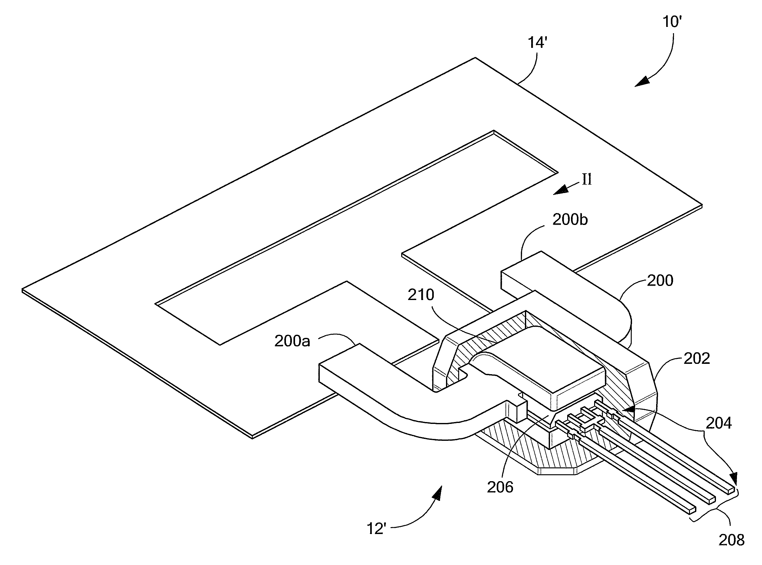
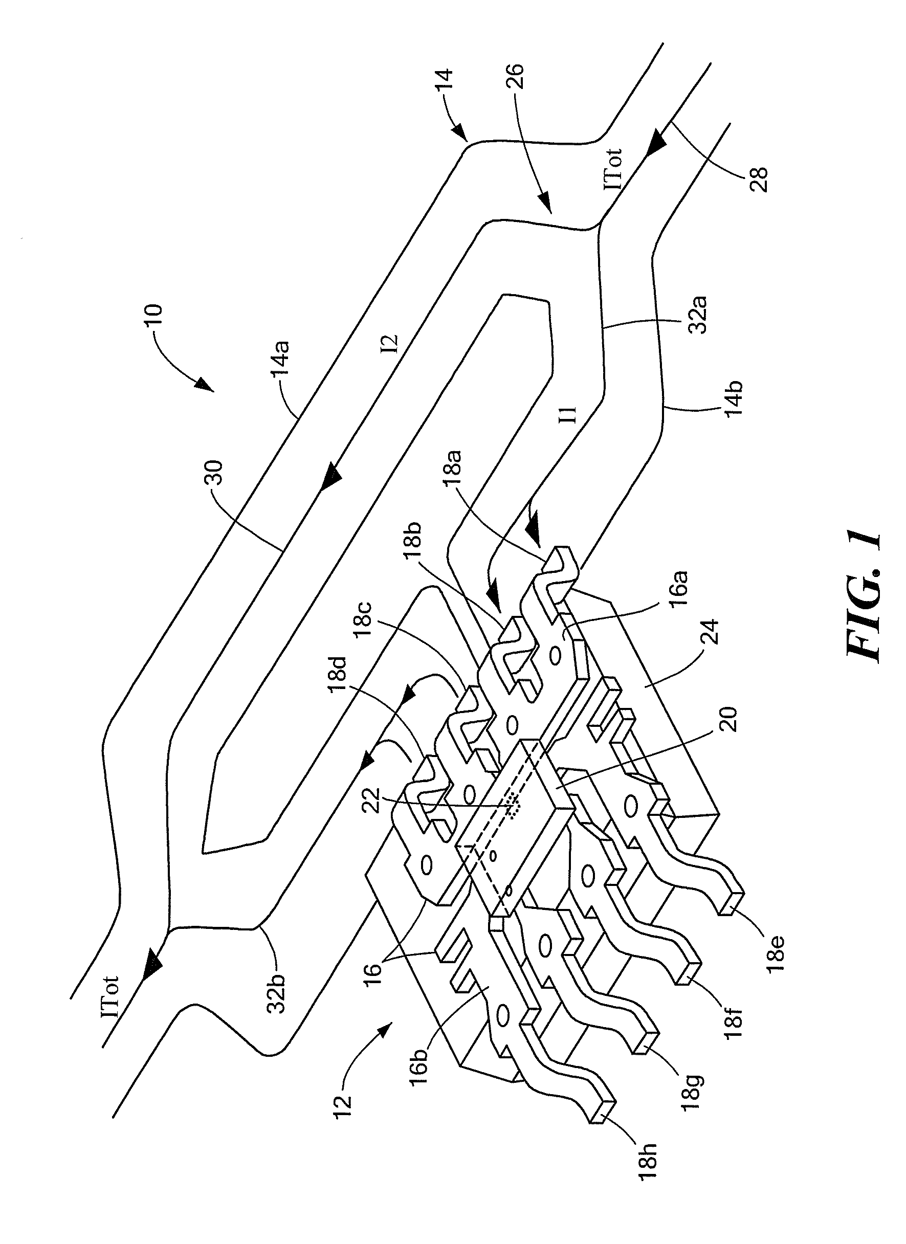
[0021]Referring to FIG. 1, an exemplary current divider current sensing configuration 10 includes a current sensor 12 coupled to a current conductor 14. The current conductor may be, for example, a printed circuit board (PCB) trace or layer or a bus bar. In a current divider configuration, as illustrated, the current conductor 14 includes a current sense conductor portion 14a and a shunt conductor portion 14b that are connected in parallel. The figure shows the internal structure of the current sensor 12, which includes a lead frame 16 having a first portion 16a that includes leads (or pins) 18a-18d and a second portion 16b that includes leads 18e-18h. The leads 18a and 18b are coupled to leads 18c and 18d to form an internal current path or conductor. The current sensor 12 also includes an integrated circuit (IC) die 20 having at least one magnetic field transducer or sensing element 22, e.g., a Hall effect element, and interface circuitry (not shown) of a magnetic field sensor pro...


PUM


Abstract

An integrated circuit (IC) current sensor that self-calibrates to adjust its signal gain when employed in a current divider configuration is presented. The current sensor includes an integrated current conductor, a magnetic field transducer, a controllable gain stage and a calibration controller. The integrated current conductor is adapted to receive a portion of a calibration current. The calibration current corresponds to a full scale current. The magnetic field transducer, responsive to the calibration current portion, provides a magnetic field signal having a magnitude proportional to a magnetic field generated by the calibration current portion. The controllable gain stage is configured to amplify the magnetic field signal with an adjustable gain to provide an amplified magnetic field signal. The calibration controller is responsive to a calibration command signal to adjust the adjustable gain of the controllable gain stage to a calibrated gain in order to provide the amplified magnetic field signal at a predetermined voltage level that corresponds to a desired current sensor output signal voltage level if the full scale current were received by the integrated current conductor.

Description

CROSS REFERENCE TO RELATED APPLICATIONS[0001]Not Applicable.STATEMENT REGARDING FEDERALLY SPONSORED RESEARCH[0002]Not Applicable.FIELD OF THE INVENTION[0003]This invention relates generally to current sensors with integrated current conductors and, more particularly, to such a current sensor for use in a current divider configuration.BACKGROUND OF THE INVENTION[0004]As is known in the art, one type of conventional current sensor uses a magnetic field transducer (for example a Hall effect or magnetoresistive transducer) in proximity to a current conductor. The magnetic field transducer generates an output signal having a magnitude proportional to the magnetic field induced by a current that flows through the current conductor. Typically, the current sensor also includes circuitry to amplify and condition the output signal of the magnetic field transducer.[0005]The magnetic field transducer and circuitry are sometimes provided as an integrated circuit (IC) in an IC package that also c...

Claims


Application Information

Patent Timeline
IPC IPC(8): G01R35/00
CPCG01R15/148G01R35/005G01R15/207
Inventor DOOGUE, MICHAEL C.MILANO, SHAUN D.
Owner ALLEGRO MICROSYSTEMS INC
Why Eureka
Try Eureka