Noise immune rc trigger for ESD protection

a technology of rc circuit and esd protection, applied in the direction of emergency protective arrangements for limiting excess voltage/current, electrical equipment, etc., can solve the problems of esd protection critical, reach a nanosecond time range, trigger a threshold voltage of some protective devices, and conventional esd trigger circuits have a constraint that they also need to remain, so as to minimize the risk of a false triggering of an esd protection circui

Active Publication Date: 2008-01-10
ATMEL ROUSSET SAS
View PDF10 Cites 63 Cited by
  • Summary
  • Abstract
  • Description
  • Claims
  • Application Information

AI Technical Summary

Benefits of technology

[0010]A present invention is a circuit that reduces an RC time constant of an ESD trigger element during normal operation, thus minimizing risk of a false triggering of an ESD protection circuit.
[0011]The present invention saves significant layout area by eliminating need of a timeout circuit associated with releasing a device maintaining a trigger state (i.e., a trigger latch). A layout area reduction is possible due to reducing the risk of false triggering due to RLC noise or IR drops caused by SSO.
[0012]The invention provides noise immune triggering elements to avoid activation of an ESD shunt device during normal powered-on operation. A RC time constant for triggering is set in an operational context according to conditions of usage. During normal operation, when a chip is powered, an ESD trigger resistor is shunted by an MOS device. The parallel combination of the ESD trigger resistor and the MOS device significantly lowers a resistive component of a first RC time constant and thus avoids triggering due to noise or SSO.

Problems solved by technology

Electrostatic Discharge (ESD) protection is a critical problem for modern integrated circuits.
However, in extreme cases during normal operation, when several outputs switch simultaneously, it is possible that a voltage drop due to noise (due to either an IR or RLC voltage drop) on a power supply line can reach a nanosecond time range and trigger a threshold voltage of some protective devices.
Additionally, conventional ESD trigger circuits have a constraint that they also need to remain on for several microseconds to be effective during an ESD upset.
In extremely noisy power supply situations, it is possible to generate a false triggering of a shunt circuit.

Method used


Image

  • Noise immune rc trigger for ESD protection
  • Noise immune rc trigger for ESD protection
  • Noise immune rc trigger for ESD protection

Examples


Embodiment Construction

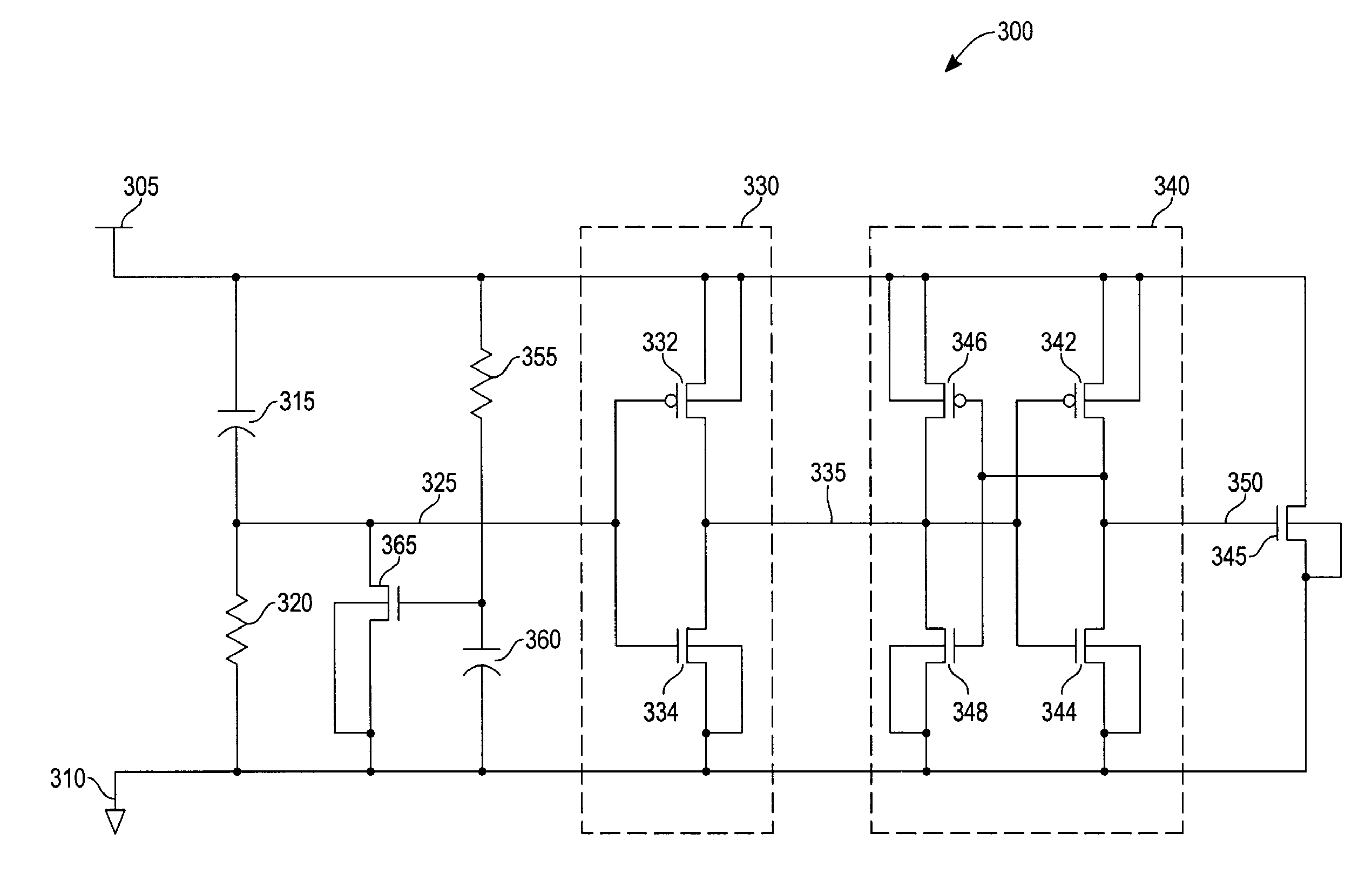
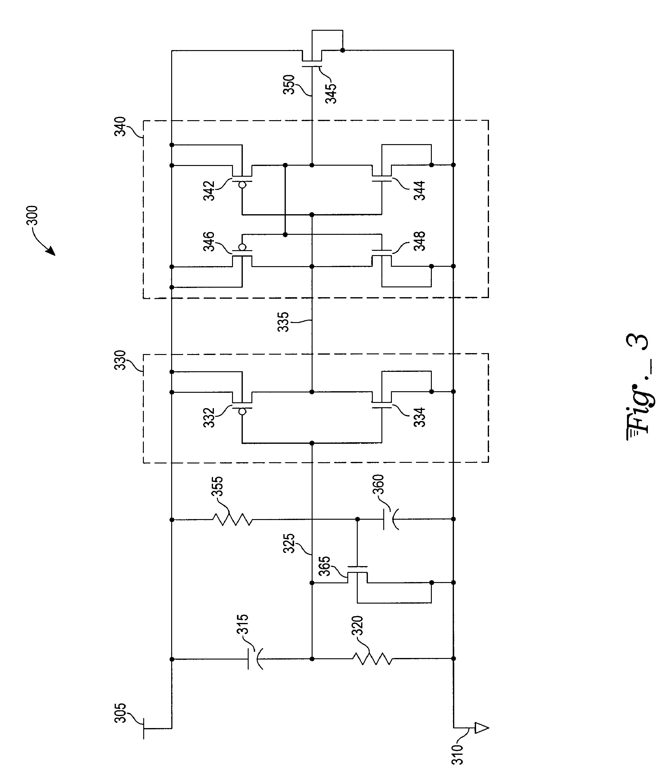
[0024]With reference to FIG. 3, a series configuration of a trigger capacitor 315 and a trigger resistor 320 connects between VDD 305 and ground 310 forming an ESD trigger network in an exemplary embodiment of an ESD protection circuit 300. An ESD inverter 330 and a trigger latch 340 each connect between VDD 305 and ground 310. An ESD trigger line 325 connects between a first series connection node (between the trigger capacitor 315 and trigger resistor 320) and an input of an ESD inverter 330. The ESD inverter 330 contains an inverter pullup device 332 in series with an inverter pulldown device 334 between VDD 305 and ground 310. The input of the ESD inverter 330 connects to a control input of both the inverter pullup device 332 and the inverter pulldown device 334. A trigger line 335 connects between an output of the ESD inverter 330 and an input of a trigger latch 340. An ESD shunt device 345 connects between VDD 305 and ground 310. An ESD shunt trigger line 350 connects between ...


PUM


Abstract

An ESD protection circuit incorporates an ESD shunt device triggered by an ESD trigger network. In non-powered situations, a first RC time constant in the ESD trigger network, corresponds with the time range of the onset an ESD event and controls application of the ESD shunt device in response to the ESD event. A second RC time constant in a shunt trigger network is selected to be longer than the first RC time constant and holds-off triggering of a shunt device during ESD shunt protection. When activated during powered-on operation, the shunt device shunts a resistive element in the ESD trigger network forming a third time constant. The shunt device guards against false triggering during noise on a power rail by maintaining the third time constant in the ESD trigger network. The third time constant ensures that power rail voltage buildup due to noise dissipates before a false trigger develops.

Description

CROSS-REFERENCE TO RELATED APPLICATION[0001]This application claims priority from U.S. provisional application No. 60 / 806,608, filed Jul. 5, 2006.TECHNICAL FIELD[0002]The invention generally relates to electrostatic discharge protection of integrated circuits. More specifically, the invention relates to an RC circuit with high noise immunity for triggering an ESD shunting device.BACKGROUND ART[0003]Electrostatic Discharge (ESD) protection is a critical problem for modern integrated circuits. With a low breakdown voltage of transistors in submicron processes, it is important to provide a method of protecting power supply pins from ESD damage, especially on smaller chips where there is no high capacitance available to absorb current from a discharge. On many circuits a method used to provide this protection is a shunt circuit that responds to a rapid rise of voltage on a power supply line by shunting a power supply line to ground during an ESD upset event.[0004]It is possible to disti...

Claims


Application Information

Patent Timeline
Patent Type & Authority Applications(United States)
IPC IPC(8): H02H9/04H02H3/20
CPCH02H9/046
Inventor BERNARD, DAVIDRIVIERE, ANTOINE
Owner ATMEL ROUSSET SAS
Why Eureka
Try Eureka