Temperature-compensated shunt current measurement

a technology of shunt current and compensation, which is applied in the direction of measuring devices, instruments, electrical testing, etc., can solve problems such as amplifier gain chang

Inactive Publication Date: 2011-04-21
TDK LAMBDA CORP
View PDF5 Cites 57 Cited by
  • Summary
  • Abstract
  • Description
  • Claims
  • Application Information

AI Technical Summary

Benefits of technology

[0034]According to an aspect of some embodiments of the present invention there is provided a method for providing a current measurement unit. The method includes: providing a current sensor having a shunt, a first terminal and a second terminal, and attaching a first resistant element between the shunt and the first terminal such that at least a portion of the first resistant element is in thermal contact with a first predetermined location subject to thermal drift on the shunt, wherein a resistance of the first resistant element varies in accordance with a temperature of the shunt, thereby to provide an output stabilized for changes in shunt temperature.

Problems solved by technology

Changes in the shunt temperature change the total resistance of the amplifier input path, ultimately resulting in a change in amplifier gain.

Method used


Image

  • Temperature-compensated shunt current measurement
  • Temperature-compensated shunt current measurement
  • Temperature-compensated shunt current measurement

Examples


Embodiment Construction

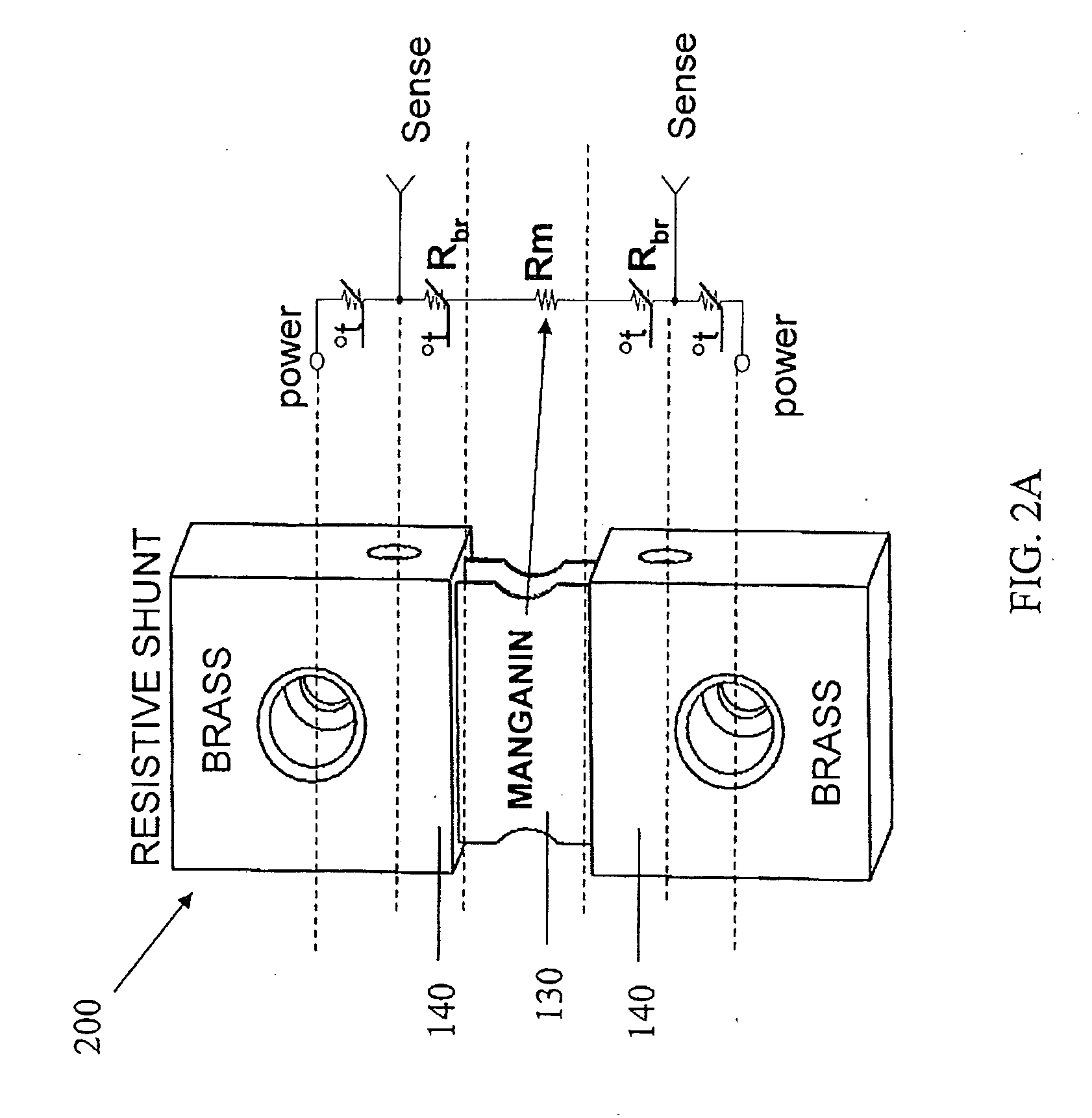
[0061]The present invention, in some embodiments thereof, relates to a shunt with a temperature-sensitive resistant element, and more particularly, but not exclusively, relates to current measurement through a shunt with compensation for temperature-related resistance changes.

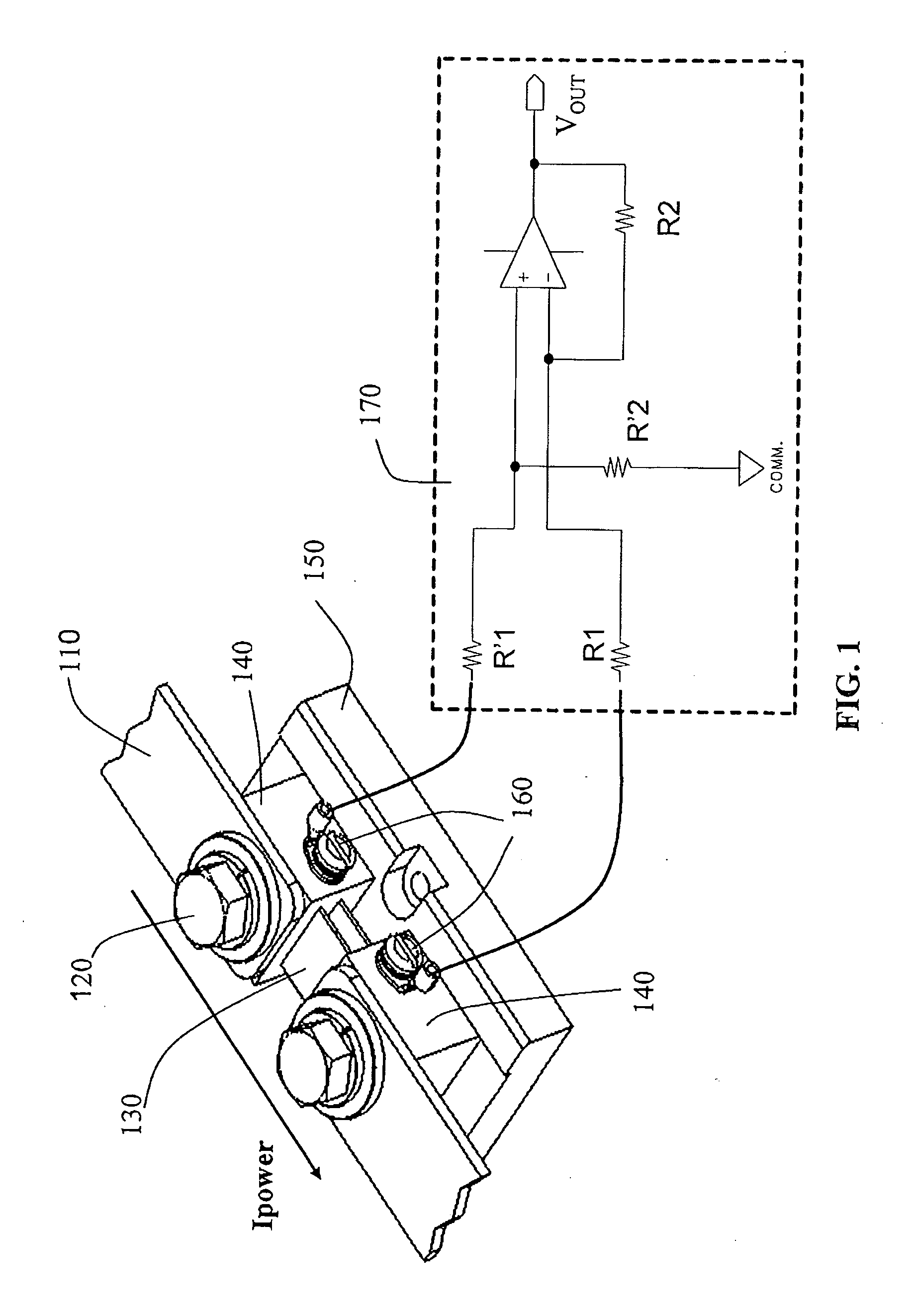
[0062]Many applications require an accurate knowledge of the amount of current being carried through a current shunt. The current is evaluated by measuring the voltage drop across the shunt, and dividing the measured voltage by a known shunt resistance. However if the shunt resistance varies with temperature, the voltage measurement will not provide an accurate measure of the current through the shunt.

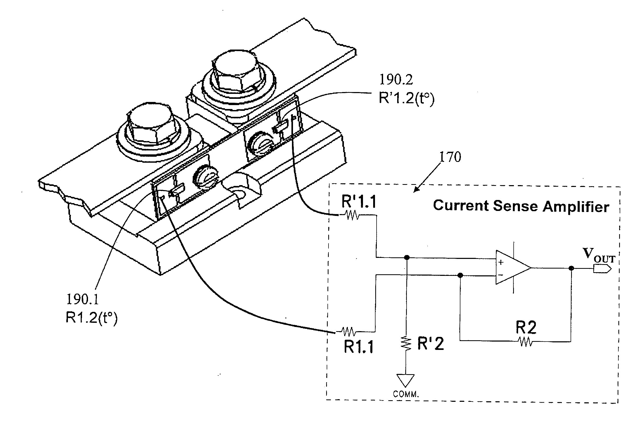
[0063]In order to compensate for the temperature-related changes in the voltage drop over the shunt, in some of the following embodiments a temperature-sensitive resistant element (such as a thermistor) is attached to the shunt. Changes in the resistance of the resistant element effectively control the gain of an ...


PUM


Abstract

A current sensor includes a shunt and at least one resistant element. The shunt conveys an electric current, and has a resistance which varies with the shunt's temperature. A resistant element, which has a resistance that varies with its own temperature, is electrically connected between the shunt and an output terminal of the current sensor. At least a portion of the resistant element is in thermal contact with a predetermined location on the shunt, so that the resistant element's resistance varies in accordance with the shunt temperature. The current sensor may be connected to an amplifier whose gain varies in accordance with the resistance of the resistant element. The variation in the resistance of the resistant element causes a change in the amplifier gain, which compensates for changes in the shunt resistance due to change's in the shunt's temperature. In some embodiments, a second resistant element is connected between the shunt and a second output terminal.

Description

FIELD AND BACKGROUND OF THE INVENTION[0001]The present invention, in some embodiments thereof, relates to a shunt with a temperature-sensitive resistant element, and more particularly, but not exclusively, relates to current measurement through a shunt with compensation for temperature-related resistance changes.[0002]Current measurement is often performed by placing a current shunt in the current pathway. The voltage drop across the shunt is measured, and the current calculated by dividing the voltage by the resistance of the shunt.[0003]In order to accurate results, the resistance of the current shunt between the sensing points must be known with high accuracy. The resistance of many materials suffers from a large change in resistance due to changes in temperature. Therefore a significant current measurement error occurs if a fixed value for resistance is used in the calculation of the current through such a shunt.[0004]This effect is sometimes overcome by using a more expensive m...

Claims


Application Information

Patent Timeline
Patent Type & Authority Applications(United States)
IPC IPC(8): G01R1/20
CPCG01R19/32G01R1/203
Inventor PODLISK, ILIARUCAREANU, GEORGE
Owner TDK LAMBDA CORP
Why Eureka
Try Eureka