Off-the-road tire

A technology for engineering vehicle tires and treads, which is applied to heavy tires, tire parts, tire treads/tread patterns, etc., can solve the problems of early tread wear, block fragmentation, etc., and achieve progress in preventing cracks , taking into account the effect of heat resistance and excellent protection

Inactive Publication Date: 2004-10-20
BRIDGESTONE CORP
View PDF0 Cites 19 Cited by
  • Summary
  • Abstract
  • Description
  • Claims
  • Application Information

AI Technical Summary

Problems solved by technology

[0006] However, in an off-the-road vehicle tire equipped with small grooves in the circumferential direction for heat dissipation, as described above, when the block row is formed in the center of the tread, each block tends to move back and forth or left and right when the load is rotated, so it cannot cope with high loads. capacity and high traction capacity requirements, leading to wear resistance related problems such as premature wear of the tread or block chipping and other failures

Method used


Image

  • Off-the-road tire
  • Off-the-road tire
  • Off-the-road tire

Examples


Embodiment 1

[0091] The OTR tires of the present invention were produced, and performance evaluations related to wear resistance, crack progression resistance, heat release performance, and traction performance were performed as described below.

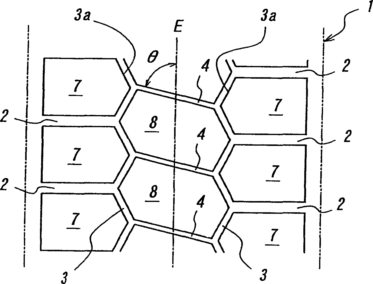
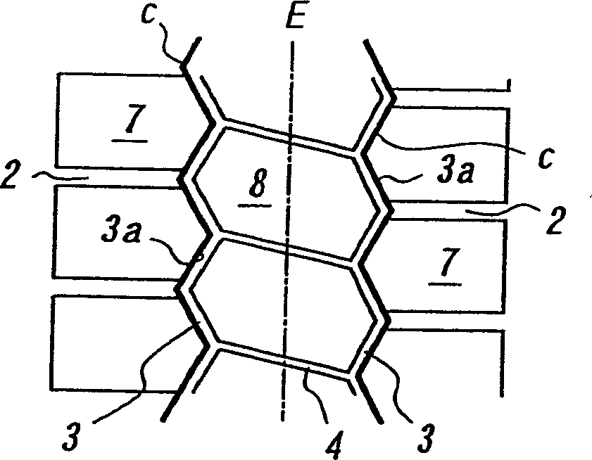
[0092] Example tire 1 has figure 1 With the tread pattern shown, Example tire 2 has the following Figure 4 With the tread pattern shown, the conventional example tire 1 has the following Figure 8 The tread pattern shown, then Conventional Example tire 2 has the following Figure 9 The tread pattern shown is shown, and embodiment tire 3 has a groove structure as shown in Figure 5, embodiment tire 4 has a groove structure as shown in Figure 5 and Figure 6, and embodiment tire 5 has a groove structure as shown in Figure 5 and Figure 6 And the trench structure shown in Figure 7.

[0093] Furthermore, each of the test tires had the specifications shown in Table 1, and the region from the bead portion to the sidewall portion had the same structure...

Embodiment 2

[0107] Find the cost of the mold when changing the type of mold and the boundary position of the mold parts, the exchange time of the separated mold parts, and measure the occurrence of the boundary position of the mold parts of the tire when the manufactured tire is rotated at a speed of 10km / h for 5000km The partial wear of the land part caused by the released rubber is shown in Table 3.

[0108] Also, the tire size and usage conditions at this time are the same as those in Example 1.

[0109] Past example

Comparative example 1

Example 1

Example 2

Example 3

Example 4

Example 5

Example 6

Comparative example 2

Type of mold

full mold

full mold

Split mold

Split mold

full+separation

full+separation

full+separation

full+separation

full+separation

Pattern Correspondence

Figure 9 (convex part)

figure 1

figure 1

figure 1

Figure 3a

Figur...


PUM

PropertyMeasurementUnit
thicknessaaaaaaaaaa
hardnessaaaaaaaaaa

Abstract

The invention is to improve wear resistance and resistance to crack growth of an off-the-road tire having a gauge of a tread rubber of 60-200 mm, in which a plurality of widthwise grooves extending substantially in a widthwise direction of the tire are arranged in each side region of the tread, and a pair of circumferential fine grooves continuously extending straight-forward or zigzag in a circumferential direction of the tire are arranged in a central zone of the tread, and a plurality of widthwise fine grooves extending substantially in the widthwise direction of the tire and contacting their grooves walls with each other in a ground contact area are arranged between these circumferential fine grooves.

Description

technical field [0001] The invention relates to an engineering vehicle tire, which is capable of taking into account the wear resistance of the tread and the resistance to crack progression under severe load conditions and traction conditions. Background technique [0002] The construction vehicle tires used for construction vehicles are also heavy-duty tires. However, compared with truck and bus tires, due to the higher load capacity and traction capacity required, these conventional tread patterns are generally In other words, the central part of the tread is formed with ribs that can exhibit wear resistance even under high loads, and the convex parts that can exhibit high traction performance are formed on both sides of the tread. [0003] However, if the width of the formation area of ​​the linear or zigzag convex portion connected to the front end of the coating groove in the central part of the tread is larger than necessary, the traction performance when climbing a sl...

Claims


Application Information

Patent Timeline
Patent Type & Authority Applications(China)
IPC IPC(8): B60C11/00B60C11/11B60C11/13
CPCB60C11/13B60C11/11Y10S152/902B60C11/00Y10S152/03B60C2200/065
Inventor 小野昭
Owner BRIDGESTONE CORP
Why Eureka
Try Eureka