Projection lens

A projection lens, lens technology, used in optical components, optics, instruments, etc.

Inactive Publication Date: 2004-11-24
SONY CORP
View PDF0 Cites 4 Cited by
  • Summary
  • Abstract
  • Description
  • Claims
  • Application Information

AI Technical Summary

Problems solved by technology

[0017] Furthermore, if the lens system forming the projection lens adopts the above-mentioned structure for changing the optical path, it is possible to suppress the height of the projection display device and reduce its dimension in the depth direction.

Method used


Image

  • Projection lens
  • Projection lens
  • Projection lens

Examples


Embodiment Construction

[0061] The projection lens of the embodiment of the present invention is described below. In the following description, the projection lens of the embodiment is provided in a projection device of a rear projection display device in which an LCD unit is used as a two-dimensional image display element.

[0062] It should be noted that the following description is made in the following order.

[0063] 1. Configuration of projection display device

[0064] 1-1. General configuration (first instance)

[0065] 1-2. General Configuration (Second Example)

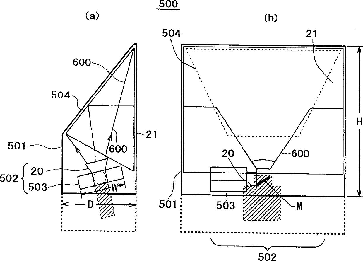
[0066] 1-3. Internal Configuration of Projection Device (First Example)

[0067] 1-4. Internal Configuration of Projection Device (Second Example)

[0068] 1-5. Internal Configuration of Projection Device (Third Example)

[0069] 2. Lens

[0070] 3. Configuration of projection lens

[0071] 3-1. Arrangement structure of lenses

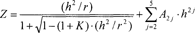
[0072] 3-2. Conditional expressions

[0073] 3-3. Numerical Examples, etc.

[0074] 1. Configu...


PUM


Abstract

A projection lens of the retrofocus type which has a long back focus, can project with a high contrast, exhibits small aberrations such as a distortion aberration and converts a light path in the inside thereof. A first lens set (0) having a negative refractive power and having light path conversion means built therein, an iris (400) and a second lens set (300) having a positive refractive power and including an aspheric lens are disposed in order from the screen side. The first lens set (0) includes a first A lens set (100) having a negative refractive power and including one or more aspheric lenses, a bending mirror (M) serving as the light path conversion means, and a first B lens set (200) having a positive refractive power. The lenses in the first A lens set have an outer shape with a portion thereof cut outside an effective light ray in a direction of the light path conversion, and the direction of the light path conversion is a direction of a shorter side of the rectangular image formation element. Where the focal length of the entire system is represented by FL, the back focus by FB, the front side focal position of the second lens set by FFP2, the distance between the iris and the second lens set by Dst, and the air converted distance on the optical axis between the first lens set and the second lens set by D2, conditional expressions [FB / FL>2.2], [0.59<|FFP2 / Dst|<0.96] and [3.75 G02B 13 / 04 G02B 13 / 18 G02B 13 / 22 25 24 0 2002 / 8 / 28 1549945 2004 / 11 / 24 1278160 2006 / 10 / 4 2006 / 10 / 4 2006 / 10 / 4 Sony Corp. Japan Sugano Yasuyuki li deshan 11038 The Patent Agency of the Chinese Council for the Promotion of International Trade (CCPIT) No.1 Waidajie, Fuxingmen, Beijing 100086 Japan 2001 / 8 / 28 258080 / 2001 2004 / 2 / 27 PCT / JP2002 / 008657 2002 / 8 / 28 WO2003 / 021326 2003 / 3 / 13 Japanese

Description

technical field [0001] The present invention relates to a projection lens, and is applicable to, for example, a projection lens provided in a projection device of a device such as a projection display device. Background technique [0002] In recent years, projection display devices have been widely used. [0003] For one such projection display device just mentioned, a rear projection type projection display device is known which projects image light from the rear side of a transmissive screen onto a transmissive screen. [0004] In the rear projection display device just described, for example, light from a white light source is collimated into luminous flux by elements such as reflectors, and the luminous flux is separated into red, green and blue luminous fluxes by dichroic mirrors. [0005] Then, the luminous fluxes of the three colors are introduced into a two-dimensional image display element (such as LCD unit; liquid crystal display unit) formed according to red, gre...

Claims


Application Information

Patent Timeline
Patent Type & Authority Applications(China)
IPC IPC(8): G02B13/04G02B13/16G02B13/22
CPCG02B13/04G02B13/22G02B13/16G02B13/18
Inventor 菅野靖之
Owner SONY CORP
Why Eureka
Try Eureka