Radio resource control-service data unit reception

A receiver and broadcast control channel technology, applied in radio/inductive link selection arrangements, electrical components, transmission control/equalization, etc., can solve the problem of reducing radio resource efficiency, increasing processing costs and battery overhead, and increasing the number of receptions, etc. question

Inactive Publication Date: 2004-12-15
INTERDIGITAL TECH CORP
View PDF0 Cites 2 Cited by
  • Summary
  • Abstract
  • Description
  • Claims
  • Application Information

AI Technical Summary

Problems solved by technology

The first issue is the latency of proper / correct reception, which can degrade the performance of system functions that require system information and / or increase the number of receptions, thereby reducing radio resource efficiency
The second problem is that if the UE L1 has to repeatedly receive, decode and process all TBs in the RRC-SDU every time an error occurs, it will increase the processing cost and battery overhead

Method used


Image

  • Radio resource control-service data unit reception
  • Radio resource control-service data unit reception
  • Radio resource control-service data unit reception

Examples


Embodiment Construction

[0031] Preferred embodiments of the present invention will now be described with reference to the drawings, wherein like symbols represent like components throughout.

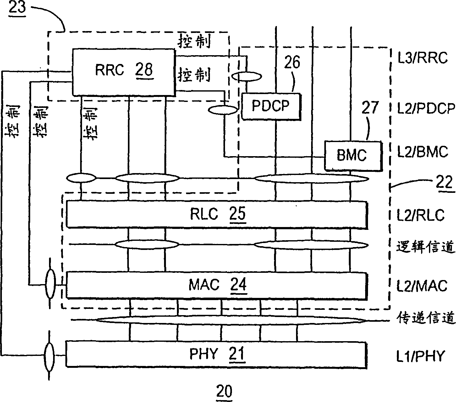
[0032] refer again Figure 4 , UE-L1 will pass the received TB group, SFN and CRC error detection result of each TB to higher layers (L2 and L3). Since both the MAC and RLC layers 24, 25 operate in BCCH transparent mode, the BCCH TB can be forwarded to L3 without further processing. It is also possible that L2 or L3 discards TBs with CRC errors before forwarding to L3.

[0033] FIG. 7 and FIG. 8 are respectively a schematic diagram and a flowchart of a method used in a preferred embodiment of the present invention. In the example shown in FIG. 7, the RRC-SDU is composed of nine (9) TBs, and the repetition period is 64 frames. The UE-BCFE will be informed in advance that the RRC-SDU is expected to have SFN=2 to SFN=18. The UE-BCFE will receive the TB group corresponding to the RRC-SDU from one of the Node Bs...


PUM


Abstract

A method for processing a received communication which includes periodic transmissions of a set of information segments. A first transmission of the set of information segments is received and processed to identify each of the segments as valid or invalid. The valid segments of the first set are then stored. Where all segments of the set are not stored, subsequent transmissions of the set of information segments are received and only those segments not previously stored are processed to identify each such segment as valid or invalid. The valid segments so identified are then stored. Subsequent transmissions are repeatedly received unless all segments of the set have been stored.

Description

technical field [0001] The invention relates to a method for processing received communications. Background technique [0002] figure 1 The global mobile telecommunications system (UMTS) network framework in comprises a core network (CN) 2, a UMTS terrestrial radio access network (UTRAN) 3 and at least one user equipment (UE) 18 (for simplicity, only one is shown in the figure UE18). There are two commonly used interfaces, the Iu interface between UTRAN and the core network, and the radio interface Uu between UTRAN and UE. [0003] The UTRAN is made up of several Radio Network Subsystems (RNS) 10,11. The two can be connected to each other through the Iur interface. Each RNS 10, 11 can be divided into a Radio Network Controller (RNC) 12, 13 and several base stations (Node Bs) 14-17. Node B14-17 will be connected to RNC12, 13 through the Iub interface. One Node B 14-17 can serve one or several cells. [0004] UTRAN3 can support FDD mode and TDD mode in the radio interfa...

Claims


Application Information

Patent Timeline
Patent Type & Authority Applications(China)
IPC IPC(8): H04B7/005H04B7/26H04W28/00H04L1/18H04L29/08H04W28/04H04W80/00
CPCH04L1/1835H04L1/1809H04B7/005
Inventor 赵怡如珍娜·史登-伯可维兹朱力欧·狄奈罗詹姆士·M·米勒卡尔·王史蒂芬·E·泰瑞
Owner INTERDIGITAL TECH CORP
Why Eureka
Try Eureka