Ultrasonic imaging device and method

A camera device and ultrasound technology, which is applied in sonic diagnosis, ultrasonic/sonic/infrasonic diagnosis, infrasonic diagnosis, etc. It can solve the problem of reduced dynamic range of blood flow velocity, shorten frame rate, shorten receiving time, and improve time resolution Effect

Active Publication Date: 2020-04-21
HITACHI HEALTHCARE MFG LTD
View PDF16 Cites 1 Cited by
  • Summary
  • Abstract
  • Description
  • Claims
  • Application Information

AI Technical Summary

Problems solved by technology

That is, when the phase difference is obtained, since phase wrapping (aliasing) occurs, a velocity with a frequency higher than the PRF cannot be recognized as a velocity with a lower frequency. As a result, the dynamic range of the blood flow velocity that can be detected may decrease. question

Method used


Image

  • Ultrasonic imaging device and method
  • Ultrasonic imaging device and method
  • Ultrasonic imaging device and method

Examples


no. 2 approach

[0110] The ultrasonic imaging device of this embodiment is characterized in that the transmission / reception sequence is independently controlled for each scanning line. That is, the transmission and reception sequence control unit of the ultrasonic imaging device according to the present embodiment independently controls the transmission interval of the ultrasonic waves transmitted a plurality of times for each ultrasonic wave in a plurality of transmission directions. In addition, the blood flow computing unit includes an averaging unit that averages blood flow information calculated using received signals obtained from ultrasonic waves in adjacent transmission directions.

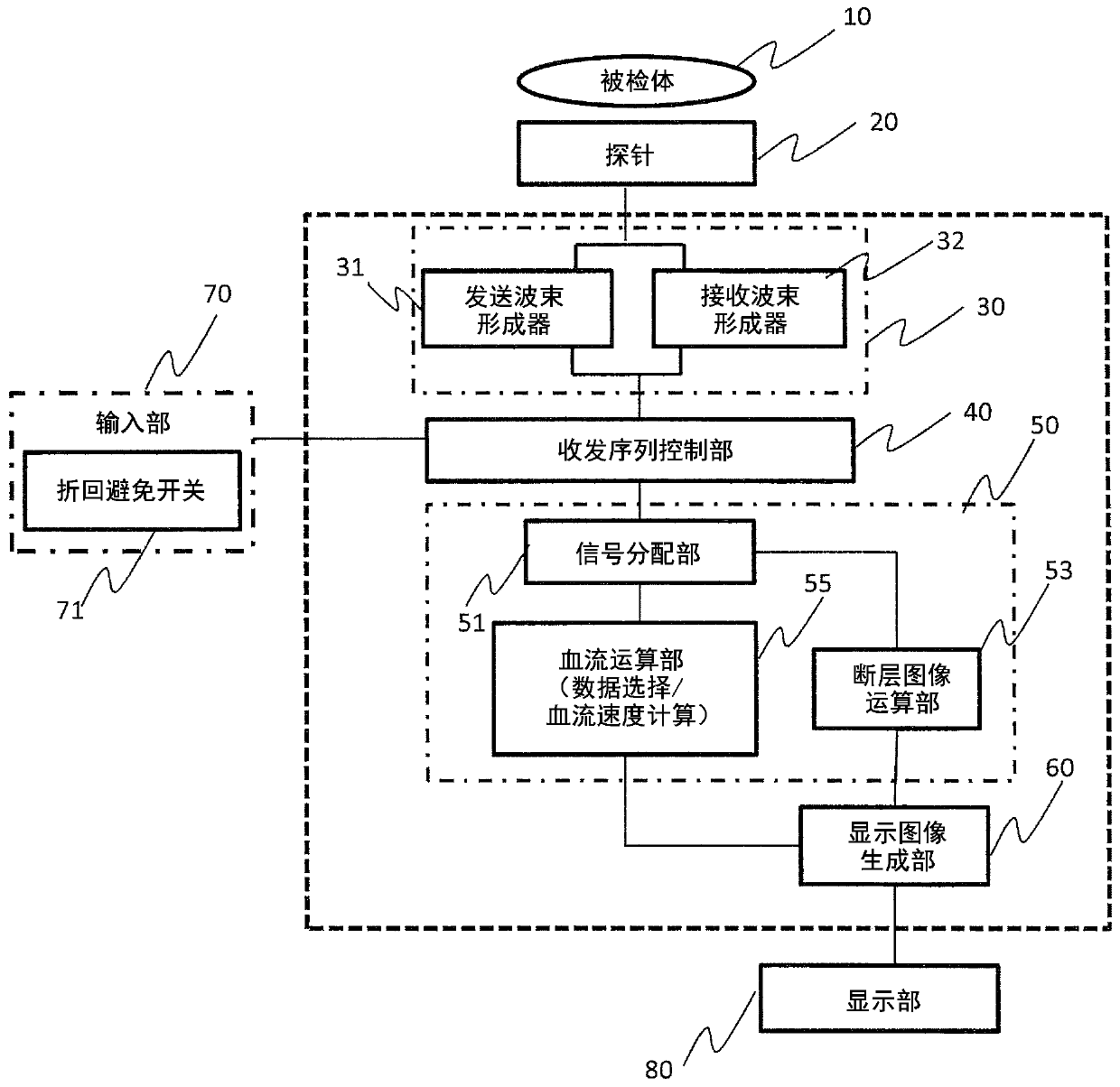
[0111] exist Figure 10 A configuration example centering on the signal processing unit of the ultrasonic imaging device according to the present embodiment is shown in . In addition, in Figure 10 , are shown with the same reference numerals as the figure 1 as well as Figure 2A The elements with the...


PUM


Abstract

Provided is a technique whereby a decline in frame rate or temporal resolution can be suppressed, and blood flow rate can be estimated in a wide rate range. On the basis of an unequal-interval transmission method, a blood flow rate is calculated using a set of temporally adjacent reception signals and a set of temporally discontinuous reception signals from among a plurality of reception signals obtained by performing transmission a plurality of times in a single transmission direction. When the number of sets of adjacent reception signals and the number of sets of temporally discontinuous reception signals are made the same, an increase in rate range the same as that of the conventional unequal-interval transmission can be realized, and the frame rate can also be enhanced.

Description

technical field [0001] The present invention relates to an ultrasonic imaging device for obtaining blood flow information of a subject, in particular to a technology for obtaining blood flow velocity information in a wide dynamic range. Background technique [0002] A color Doppler method is known as a method for acquiring blood flow information in an ultrasonic imaging device. In the color Doppler method, ultrasonic waves are sent multiple times in the same direction at a given repetition time (PRT: Pulse Repetition Time, pulse repetition time), and the frequency of the received signal received from the measurement area is calculated corresponding to each ultrasonic wave. Analyze to obtain blood flow information. In frequency analysis, for example, the phase difference (Doppler frequency shift) between temporally adjacent received signals is obtained, and the Doppler frequency shift is obtained by autocorrelation calculation of the phase difference, and the blood flow velo...

Claims


Application Information

Patent Timeline
Patent Type & Authority Applications(China)
IPC IPC(8): A61B8/06
CPCA61B8/06A61B8/488A61B8/461A61B8/5223A61B8/14
Inventor 浅见玲衣
Owner HITACHI HEALTHCARE MFG LTD
Why Eureka
Try Eureka