
Radio-controlled timepiece and method of changing the waveform discrimination standard

A technology for judging benchmarks and waveforms. It is used in clocks, electromechanical clocks, and radio-controlled timers. It can solve problems such as inability to correctly identify and process waveforms, save power consumption, shorten receiving time, and reduce identification error codes. Effect

Inactive Publication Date: 2008-02-27
SEIKO EPSON CORP
View PDF1 Cites 1 Cited by
  • Summary
  • Abstract
  • Description
  • Claims
  • Application Information

AI Technical Summary

Problems solved by technology

In this case, the waveform discrimination process cannot be performed correctly, and a code other than "0" is output.

Method used


Image

  • Radio-controlled timepiece and method of changing the waveform discrimination standard
  • Radio-controlled timepiece and method of changing the waveform discrimination standard
  • Radio-controlled timepiece and method of changing the waveform discrimination standard

Examples


no. 1 Embodiment approach

[0070] A radio-controlled timepiece according to a first embodiment of the present invention will be described.

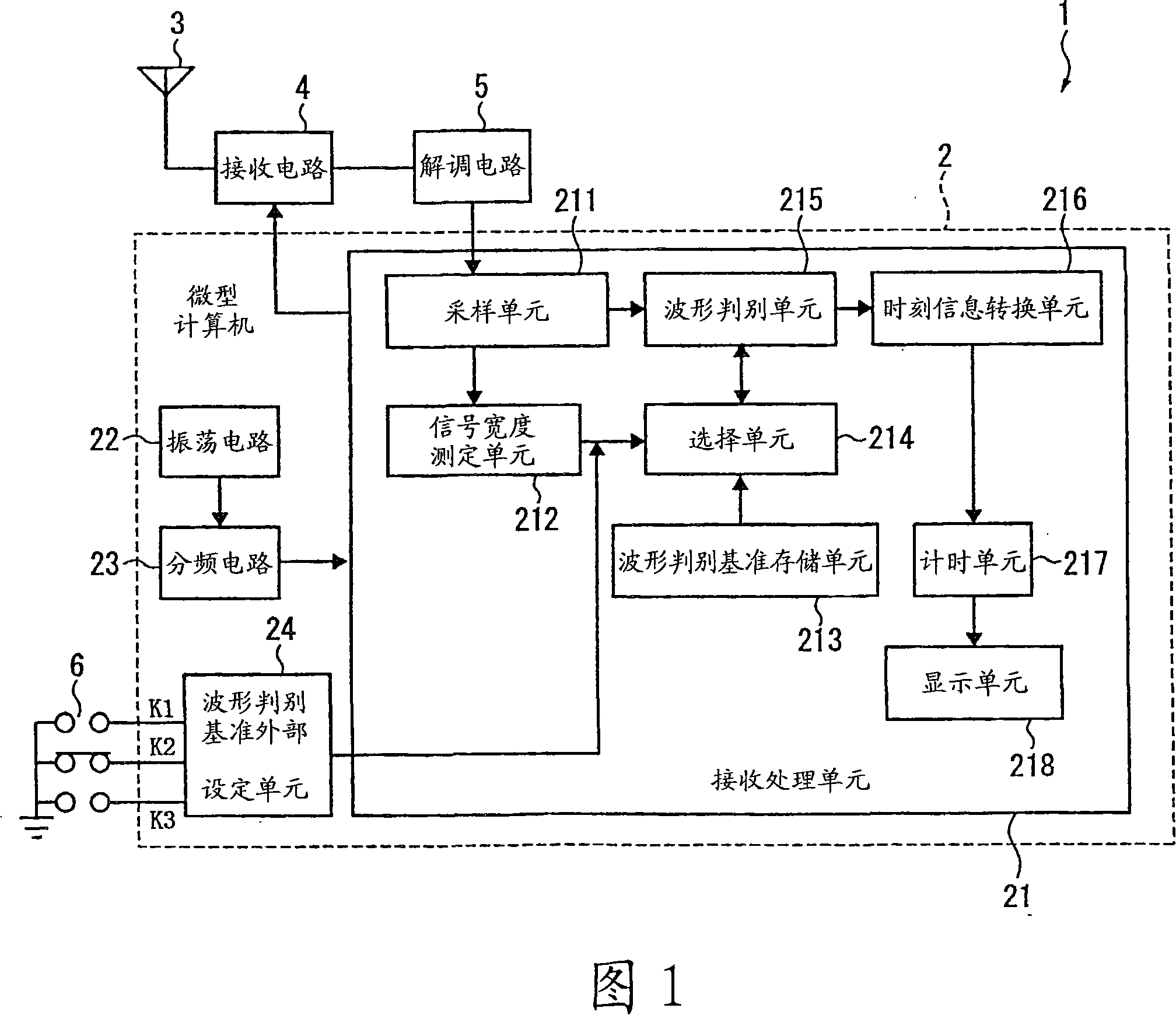
[0071]As shown in FIG. 1 , a radio-controlled timepiece 1 has a microcomputer 2, an antenna 3, a receiving circuit (receiving unit) 4 for receiving a long-wave standard radio wave via the antenna 3 according to a control signal output from the microcomputer 2, and a signal to be received by the receiving circuit 4. A demodulation circuit (demodulation unit) 5 and a jumper switch 6 for demodulating long-wave standard radio waves into time code signals.

[0072] The microcomputer 2 has a reception processing unit 21 that transmits a control signal to the reception circuit 4 and receives a time code signal demodulated by the demodulation circuit 5, an oscillation circuit 22 that generates a reference clock, and divides the frequency of the reference clock generated by the oscillation circuit 22. And it is supplied to the frequency division circuit 23 of the reception ...

no. 2 Embodiment approach

[0124] Next, a radio-controlled timepiece according to a second embodiment of the present invention will be described.

[0125] In addition, in the following description, the same code|symbol is attached|subjected to the part already demonstrated, and the description is abbreviate|omitted.

[0126] In the radio-controlled timepiece 1 of the above-mentioned first embodiment, the receiving circuit 4 receives a reference signal that repeats a predetermined code of the long-wave standard radio wave, and switches jumpers based on the signal width of the demodulated reference signal measured by the signal width measuring unit 212. The connection of the switch 6 changes the waveform discrimination criteria, but the radio wave calibration timepiece 1 of this embodiment is different in the following respects as shown in FIG. The measured signal width of the demodulated signal automatically changes the waveform discrimination criterion.

[0127] Furthermore, in the present embodiment, ...


PUM


Abstract

A radio-controlled timepiece has a reception means that receives a standard radio signal containing time information; a demodulation means that demodulates the standard radio signal received by the reception means and outputs a demodulated signal; a waveform discrimination means that discriminates the waveform of the demodulated signal based on a specific waveform discrimination standard, and outputs a code corresponding to the waveform; a time information conversion means that converts the code output by the waveform discrimination means to time information; and a waveform discrimination standard changing means for changing the waveform discrimination standard.

Description

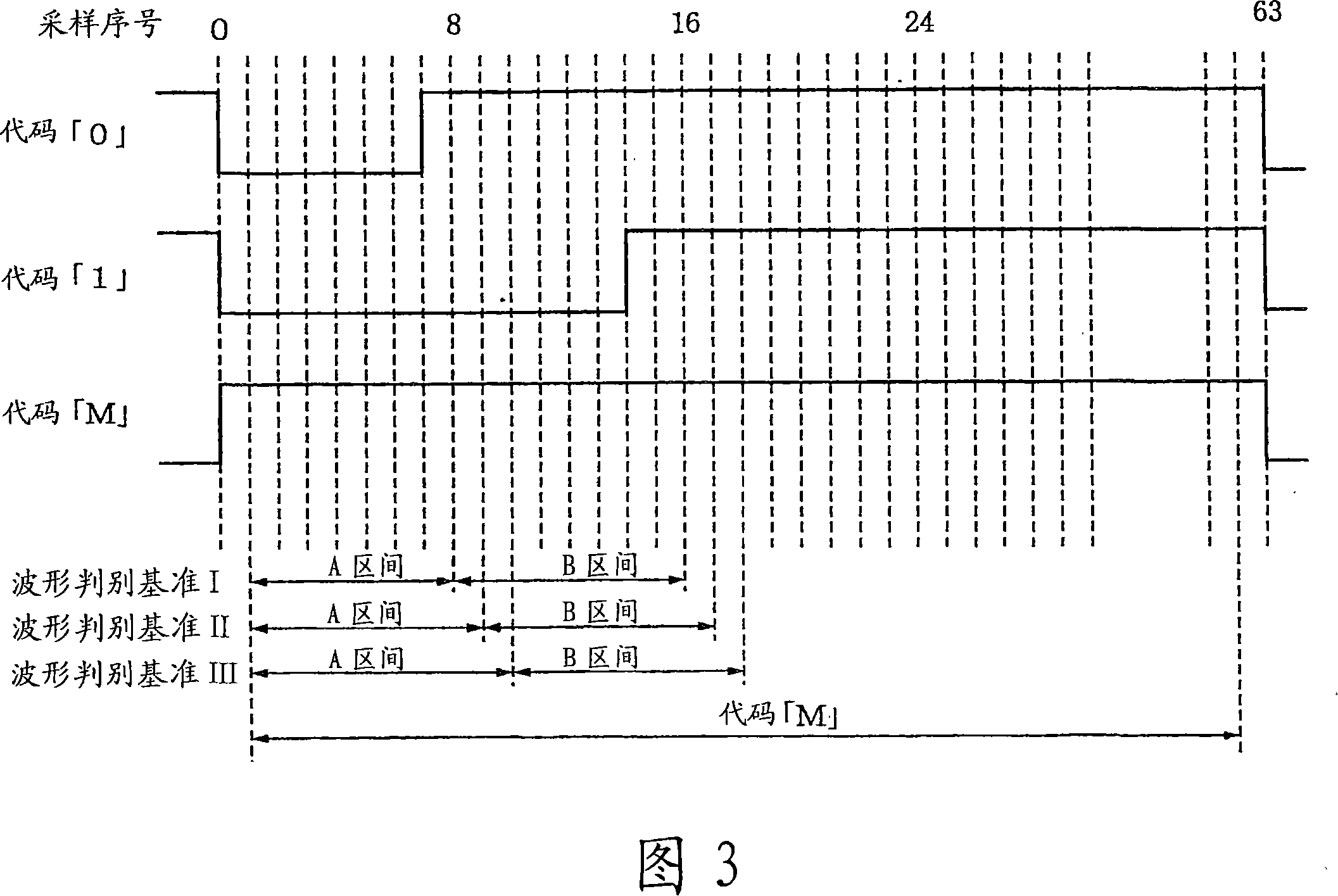
technical field [0001] The present invention relates to a radio wave calibrated clock and a method for changing its waveform discrimination standard. Background technique [0002] In recent years, in Germany, the United Kingdom, the United States, Japan and other countries, the following radio-calibrated timepieces have been popularized. This radio-controlled timepiece transmits time information at a frequency of about tens of kHz as a transmission wave, that is, transmits the so-called long-wave standard radio wave, and uses this long-wave Standard radio waves perform time calibration. The long-wave standard radio waves transmit pulse waveforms representing codes such as "0", "1", and "M" every second, and one frame is defined as one minute. Furthermore, time information such as "year", "hour", and "minute" is included in this frame. [0003] Therefore, the radio-controlled timepiece detects the pulse waveform corresponding to each code from the long-wave standard radio w...

Claims


Application Information

Patent Timeline
Patent Type & Authority Applications(China)
IPC IPC(8): G04G5/00G04C9/02G04R20/00G04R20/12
CPCG04G21/04G04R20/12G04G5/002
Inventor 清水荣作
Owner SEIKO EPSON CORP
Learn More