Radio corrected clock

Inactive Publication Date: 2008-08-05
CITIZEN WATCH CO LTD
View PDF15 Cites 2 Cited by
  • Summary
  • Abstract
  • Description
  • Claims
  • Application Information

AI Technical Summary

Benefits of technology

[0011]Further, if the radio correcting timepiece further comprises judging means for judging whether each signal reception in each signal receiving order is completed or uncompleted, and the signal receiving means terminates the signal reception by a completing signal from the judging means, the signal receiving time can be further shortened and power consumption can be saved and reduced.
[0012]Further, the radio correcting timepiece may further comprise judging means for judging whether each signal reception in each signal receiving order is completed or uncompleted, and flag judging means which sets-on a flag with respect to a standard radio wave station of this order by an uncompleting signal from the judging means, and skips the signal receiving order of the standard radio wave station having the flag at the next signal receiving time, and performs the signal reception of the next signal receiving order. In this case, power consumption can be reduced in a higher degree and the signal receiving time can be shortened by making the best use of the past signal receiving hysteresis information.
[0013]Further, the radio correcting timepiece may further comprise judging means for judging whether each signal reception in each signal receiving order is completed or uncompleted, and flag judging means which sets-on a flag with respect to a standard radio wave station of this order by a signal reception completing signal of constant or more time information from the judging means, and executes the signal reception of the standard radio wave station of the signal receiving order having the flag at the next signal receiving time. In this case, p

Problems solved by technology

However, in an area such as a Kyushu district, etc. separated by 1000 Km or more from the transmission station of the Fukushima prefecture, the intensity of an electric field is weak and there are areas unable to sufficiently receive the standard radio wave.
However, although JP-A-11-160464 discloses the solar energy operating type wireless control timepiece and JP-A-2

Method used


Image

  • Radio corrected clock
  • Radio corrected clock
  • Radio corrected clock

Examples


first embodiment

(1) First Embodiment Mode

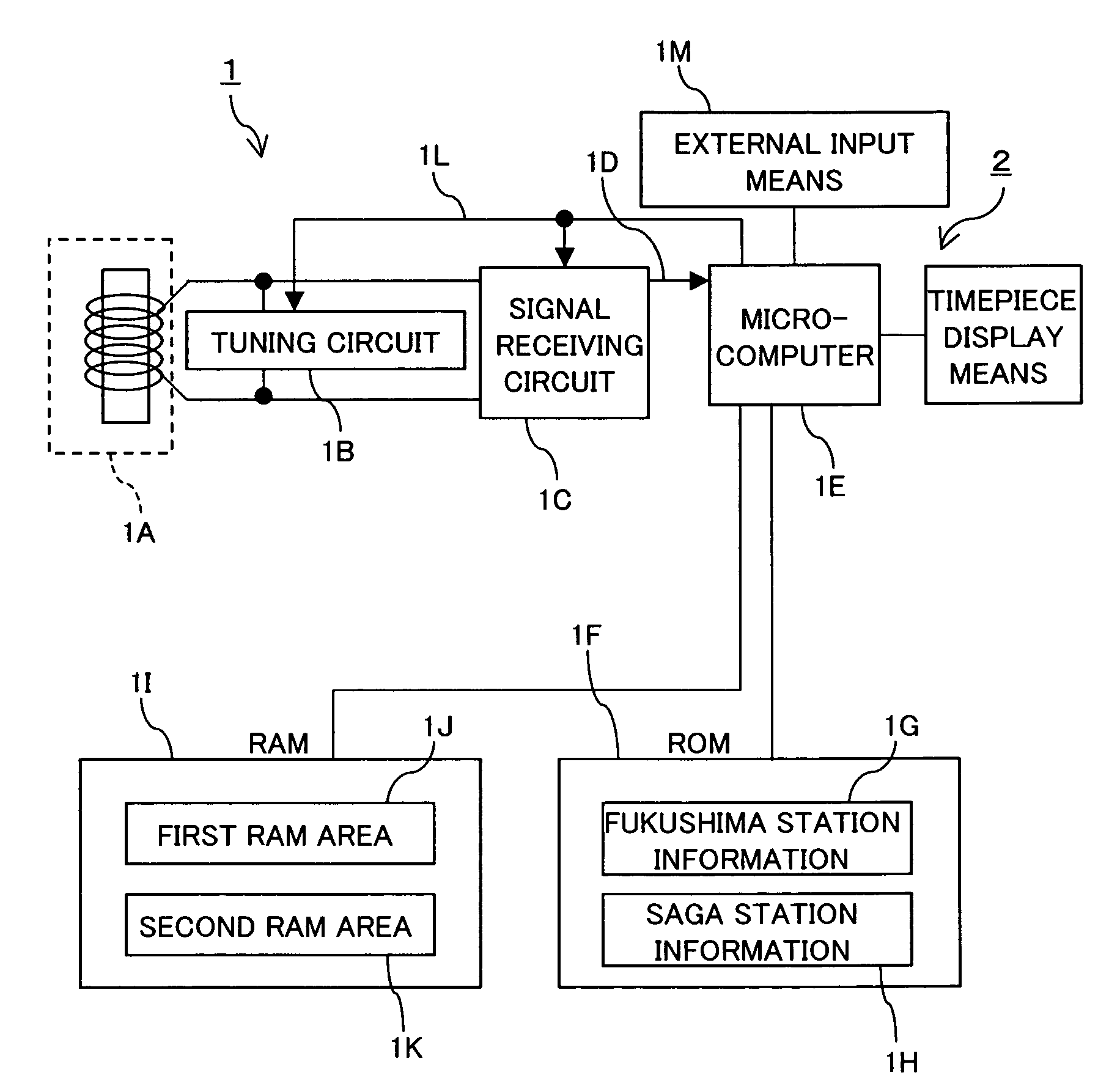
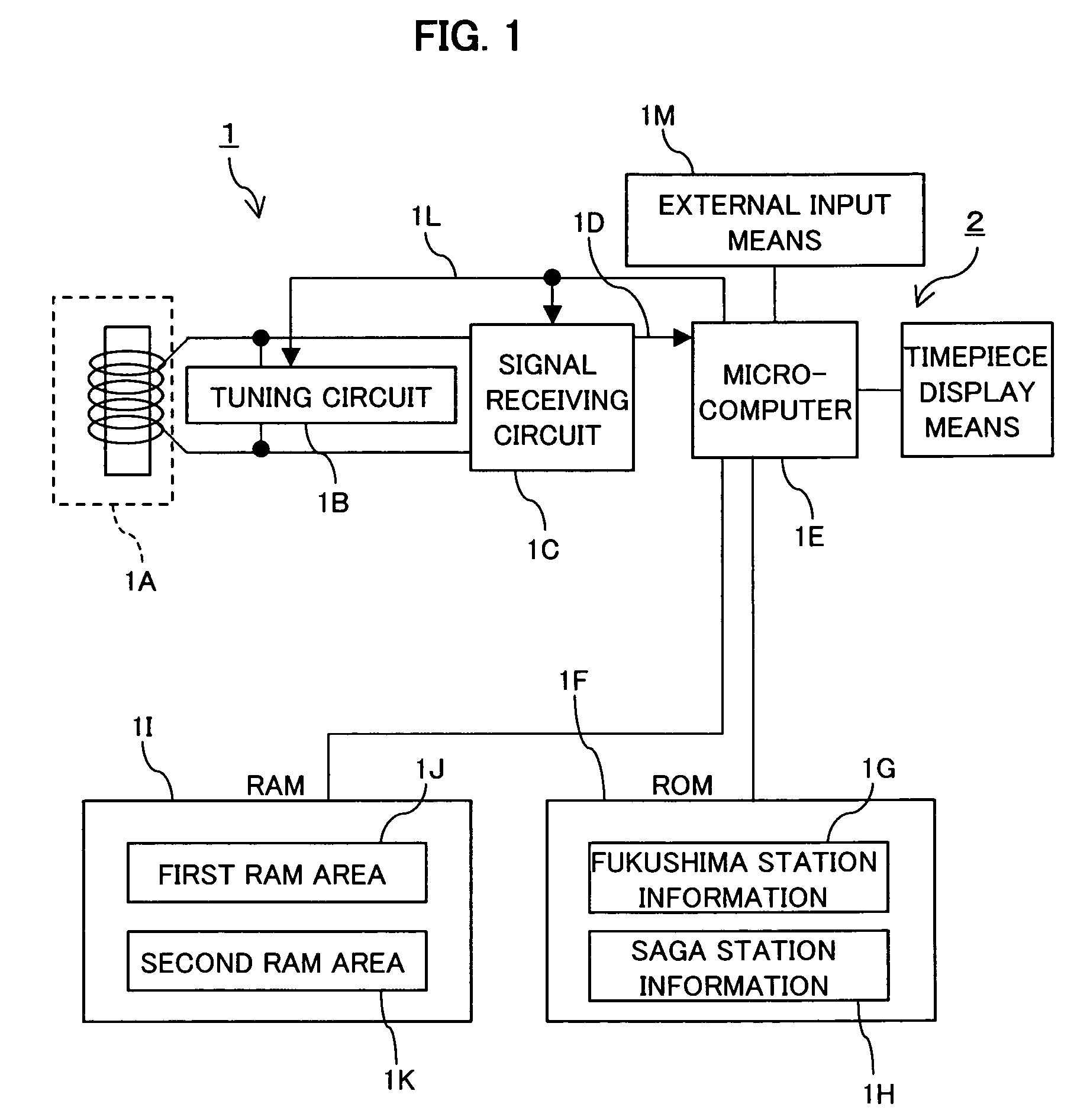
[0025]FIG. 1 is a circuit block diagram showing the first embodiment mode. In a receiving means 1 of FIG. 1, an antenna 1A receives a standard radio wave and a tuning circuit 1B tunes a tuning frequency of the antenna 1A, and the standard radio wave received by the antenna 1A is converted into a digital signal by a signal receiving circuit 1C. The digital signal 1D outputted from the signal receiving circuit 1C is inputted to a microcomputer 1E for assigning a receiving frequency and decoding the digital signal 1D and making the time correction of a timepiece means 2 for displaying time. A ROM 1F stores the receiving frequency, an algorithm, information for processing time information such as a year, a month, a day, an hour, a minute, etc. The ROM 1F stores, in this embodiment mode, the contents that the frequency transmitted from Fukushima prefecture is 40 KHz, the algorithm, Fukushima station information 1G describing the information for processing the tim...

second embodiment

(2) Second Embodiment Mode

[0036]A second embodiment mode will next be explained on the basis of FIG. 3. FIG. 3 is a flow chart showing a signal receiving step in the second embodiment mode of the radio correcting timepiece in this invention.

[0037]This embodiment is an example about the radio correcting timepiece in which a signal is mainly received in Japan. A start S21 is made by a timing signal from a timepiece means, etc., and an automatic signal receiving state is started in a step S22. First, the signal reception of the 40 KHz format of the Fukushima station is tried. When it is judged in a step S23 that the signal reception is unsuccessful and the judgment is NO, the signal reception of the 60 KHz format of the Saga station is subsequently tried in a step S24. Further, when the signal reception is unsuccessful and the judgment is NO in a step S25, the signal reception of a 60 KHz format of a US station is tried in a step S26. In this example, the signal reception is terminated...

third embodiment

(3) Third Embodiment Mode

[0039]A third embodiment mode will next be explained on the basis of FIG. 4. FIG. 4 is a flow chart showing a signal receiving step in the third embodiment mode of the radio correcting timepiece in this invention.

[0040]In this example, the signal reception of a station having a ceasing hysteresis on the way in the signal reception is not tried but passed at the next signal receiving time, and it proceeds to the signal reception of the next station.

[0041]A start step S31 is started by a timing signal from a timepiece means, etc., and an automatic receiving state is started in a step S32 and the signal reception of the 40 KHz format of the Fukushima station is intended to be first tried. It is judged in a step S33 whether a midway signal receiving flag Ffn corresponding to the Fukushima station described later is 1 or 0. If this flag is 1, this station is passed. In contrast to this, if this flag is 0, the signal reception is started and it is judged in a step...


PUM


Abstract

A radio correcting timepiece that can reduce the influence of a radio wave situation of the standard radio wave having time information according to an area, and can make a correction to the exact time in a shorter time is provided. The radio correcting timepiece comprises a signal receiving means (1) for receiving a standard radio wave and a timepiece means (2) for correcting and displaying time on the basis of the time information outputted from the signal receiving means. The signal receiving means (1) can receive plural standard radio waves and includes memory means (1I) which is able to store signal receiving order of the plural standard radio waves. Since the plural standard radio waves can be received, the influence of a radio wave situation according to an area can be reduced and a correction to the exact time can be made in a shorter time by using the standard radio wave transmitted every minute.

Description

TECHNICAL FIELD[0001]This invention relates to a radio correcting timepiece having a signal receiving means for receiving a standard radio wave having time information, and a timepiece means for displaying the time on the basis of the time information outputted from this signal receiving means. This invention particularly relates to its receiving system.BACKGROUND ART[0002]JP-A-11-160464 conventionally discloses a solar energy operating type wireless control timepiece and JP-A-2001-166071 discloses a self electricity generating type electronic timepiece. Each timepiece receives the standard radio wave including the time information of high accuracy such as a year, a month, a day, an hour, a minute, a correct second, summer time information, etc. transmitted every one minute as a technique for receiving time data from the exterior and correcting the time displayed at present, and automatically makes a time correction as time setting, a date correction, etc.[0003]In Japan, the standar...

Claims


Application Information

Patent Timeline
IPC IPC(8): G04C11/02H04L7/00G04R20/08G04G5/00G04G21/04G04R20/00
CPCG04G5/002G04R20/12G04R20/10G04G21/04
Inventor IHARA, TAKASHISAKUYAMA, MASAOTAKADA, AKINARINAMEKAWA, MASAAKI
Owner CITIZEN WATCH CO LTD
Why Eureka
Try Eureka