Circuit for testing a usb device using a packet to be measured controlled by test signals

一种测试电路、测试信号的技术,应用在电数字数据处理、错误检测/纠正、检测有故障的计算机硬件等方向,能够解决长时间、LSI成本影响较大、工时数和调试需要很多时间等问题,达到时间缩短、削减工时数的效果

Inactive Publication Date: 2008-04-02
LAPIS SEMICON CO LTD
View PDF2 Cites 1 Cited by
  • Summary
  • Abstract
  • Description
  • Claims
  • Application Information

AI Technical Summary

Problems solved by technology

Therefore, especially when the system LSI is mass-produced, if the test is started by receiving these packets that are not subject to measurement, it takes a long time to receive these packets, and the length of the test time greatly affects the cost of the LSI.
[0016] In addition, in these conventional USB devices having a USB test function, in order to create a plurality of test patterns for groups that are not subject to measurement, a lot of man-hours and debugging (debugging) are required.

Method used


Image

  • Circuit for testing a usb device using a packet to be measured controlled by test signals
  • Circuit for testing a usb device using a packet to be measured controlled by test signals
  • Circuit for testing a usb device using a packet to be measured controlled by test signals

Examples


Embodiment Construction

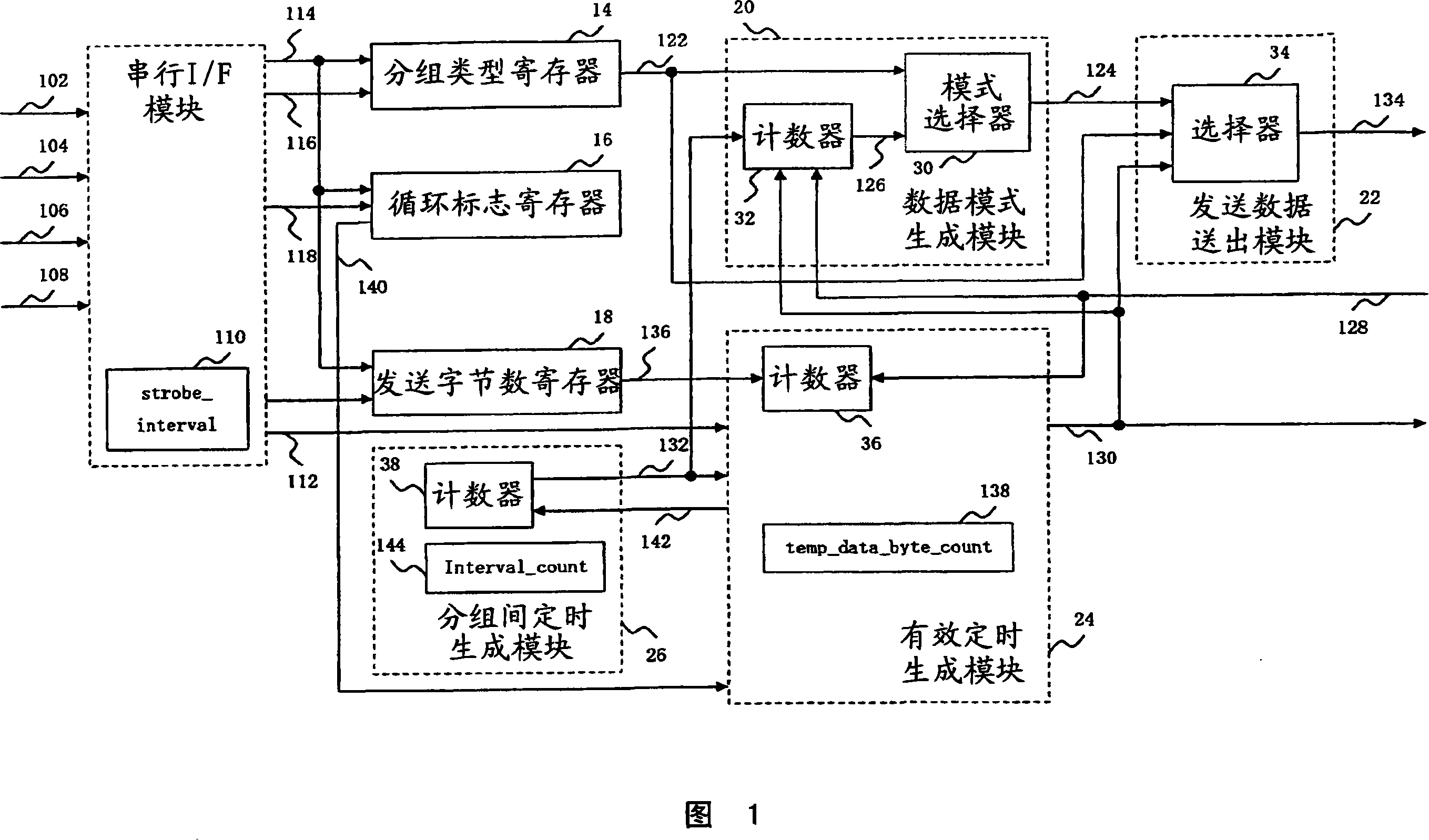
[0034]Hereinafter, embodiments of the USB test circuit of the present invention will be described in detail with reference to the accompanying drawings. For example, as shown in FIG. 1, the USB test circuit 10 of the present invention inputs a signal representing information relevant to the operating mode of the circuit to the serial I / F module 12, and keeps the information in the packet type register 14, loop flag In the register 16 and the number of bytes to send register 18, the data pattern (pattern) generating module 20 and the sending data sending module 22 generate the sending data as the measurement object packet conforming to the information, and in addition, the valid timing generating module 24 generates the sending data Timing when data is valid. In addition, in this circuit 10 , the output interval when the transmission data is repeatedly output is determined by the inter-packet timing generation module 26 . In addition, parts not directly related to the understa...


PUM


Abstract

A USB test circuit for use in a USB device such as a system LSI with a USB function for testing the USB function generates and outputs a packet to be measured for a signal quality test. In the test circuit, a test signal including a test_sin signal carrying operation mode information is inputted via a serial interface to a serial interface block, and a packet to be measured is generated by a data pattern generation block and a transmission data delivery block depending on the operation mode information. The packet to be measured is outputted via a UTMI interface to a USB PHY layer. Thus, a packet to be measured for a signal quality test is generated and outputted without receiving packets not to be measured such as a SETUP packet and a DATA packet, thereby reducing the test time.

Description

technical field [0001] The present invention relates to a USB test circuit for testing the USB function of a USB device such as a system LSI (Large Scale Integration) having a USB (Universal Serial Bus: Universal Serial Bus) function. Background technique [0002] Conventionally, the system LSI has a built-in CPU (Central Processing Unit: central processing unit) to operate. The CPU is connected to other circuits via the system bus to execute the functions of the circuit. A USB device controller (Device Controller) is connected to the bus. And a USB physical layer (PHYsical Layer: PHY) is connected to this controller to have a USB function. The CPU is capable of performing data reading and writing to registers of the USB device controller. [0003] The USB PHY is connected to a USB device controller via, for example, UTMI (USB2.0 Transceiver Macrocell Interface), and connected to an external device via USB I / F. In addition, the USB PHY has a UTMI I / F controller module, con...

Claims


Application Information

Patent Timeline
Patent Type & Authority Applications(China)
IPC IPC(8): G06F11/267G06F13/00G06F13/38
CPCG06F11/221G06F11/22G06F11/263G06F11/267
Inventor 长野真人
Owner LAPIS SEMICON CO LTD
Why Eureka
Try Eureka