Image display apparatus

A technology for image display equipment and display parts, applied in image communication, static indicators, instruments, etc., can solve the problems of manufacturers refusing to adopt, AM radio broadcasting cannot be heard clearly, and interference with public broadcasting, etc.

Inactive Publication Date: 2005-02-09
KK TOSHIBA
View PDF1 Cites 7 Cited by
  • Summary
  • Abstract
  • Description
  • Claims
  • Application Information

AI Technical Summary

Problems solved by technology

In this case, AM radio broadcasts may not be heard clearly
Furthermore, since the AM radio band is not included in the legal limit on electromagnetic interference, the manufacturer refuses to take action
As mentioned above, existing PDPs have the disadvantage of seriously interfering with public broadcasts, such as AM radio broadcasts

Method used


Image

  • Image display apparatus
  • Image display apparatus
  • Image display apparatus

Examples


no. 1 example

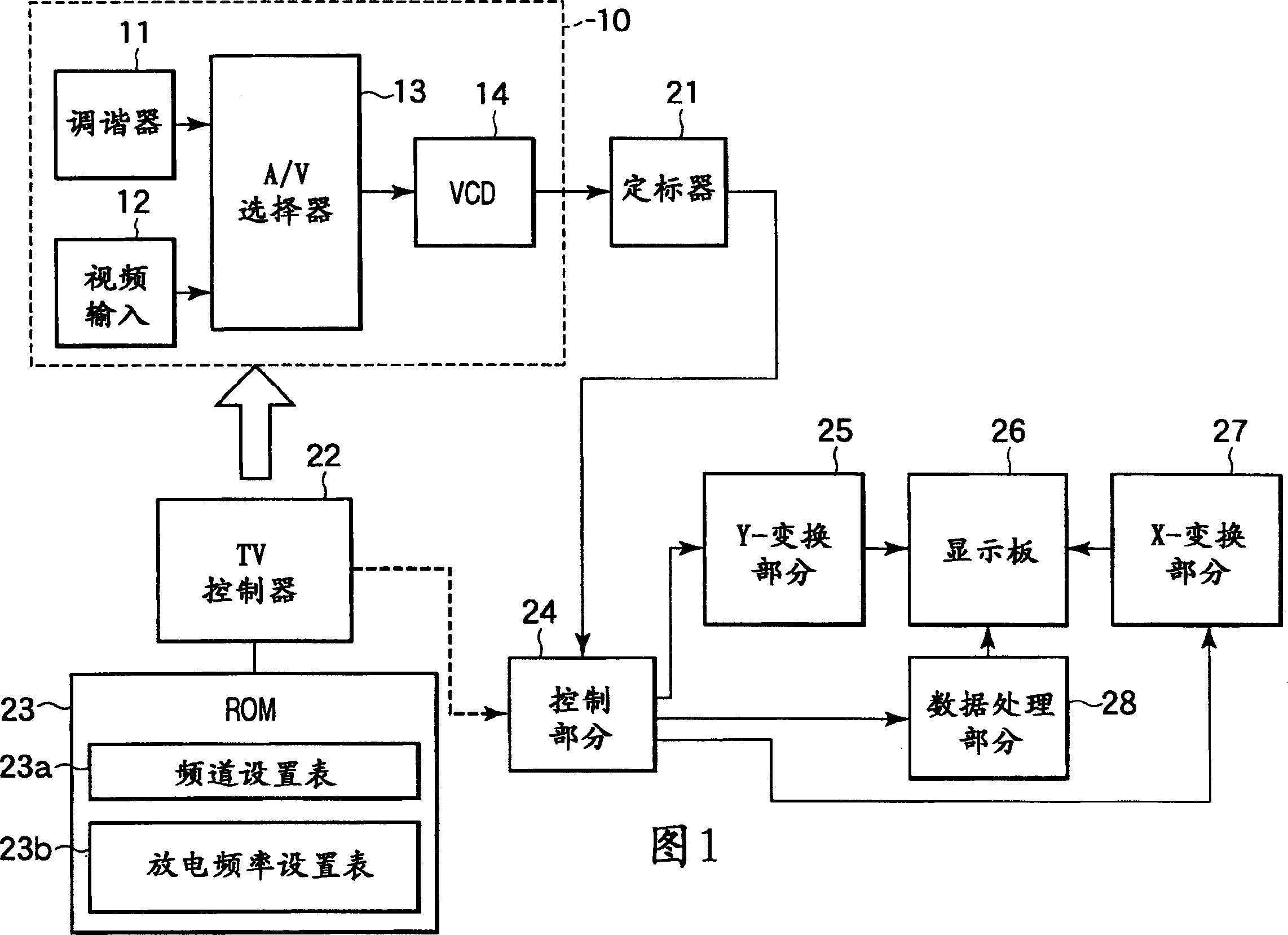
[0022] FIG. 1 is a functional block diagram of a first embodiment of an image display device according to the present invention. In FIG. 1, an output signal from a signal processing section 10 is supplied to a control section 24 through a scaler. The signal processing section 10 is controlled by a TV controller 22 based on data stored in a read only memory (ROM) 23 .

[0023] The control section 24 collects various data from the video signal and supplies the data to the data processing section 28 . Video signals are also supplied to the Y-transform section 25 and the X-transform section 27 . The Y-transform section 25 and the X-transform section 27 compress and expand the viewable size according to the size of the display panel 26 . The data processing section 28 controls the display panel 26 based on the supplied data.

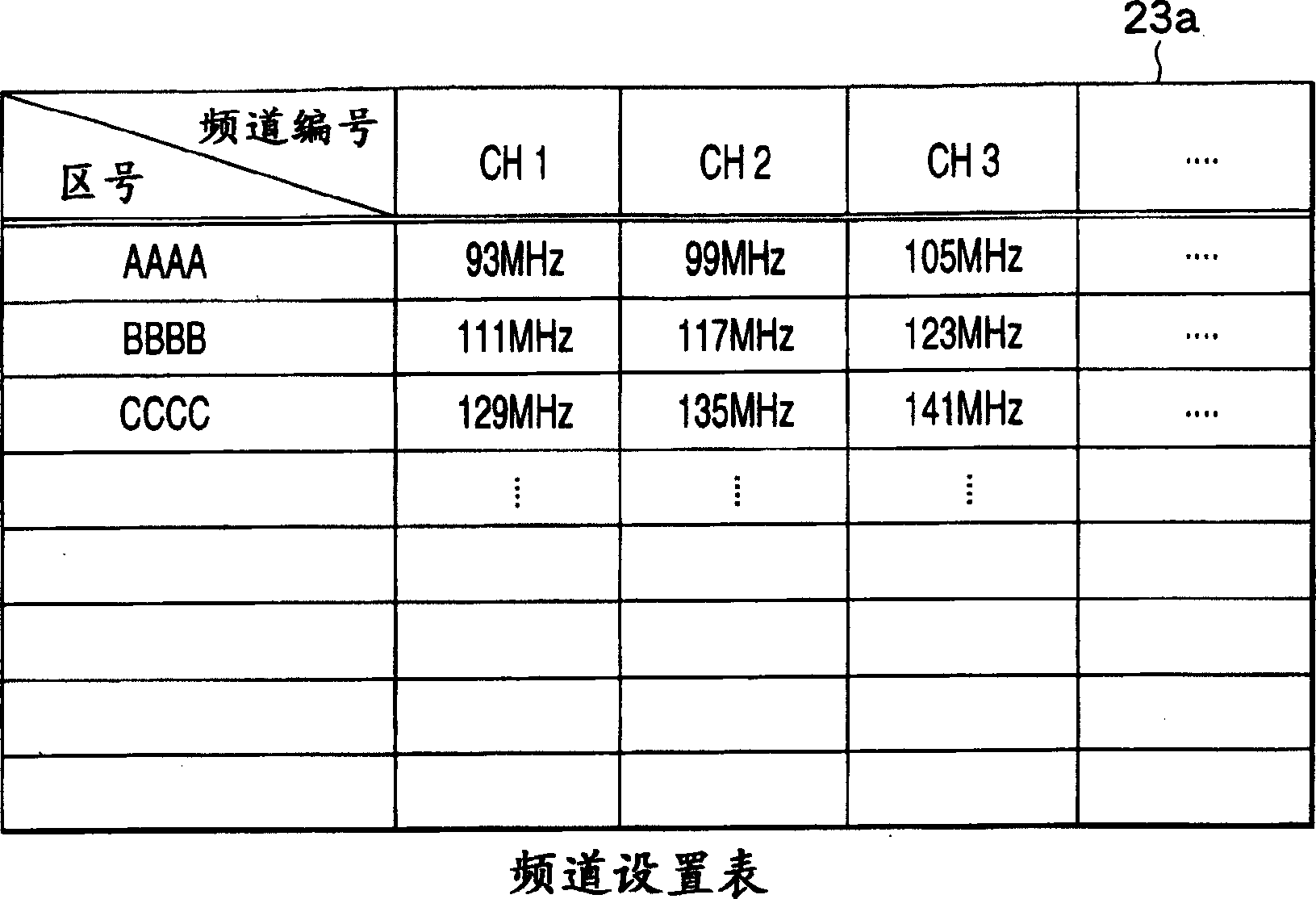
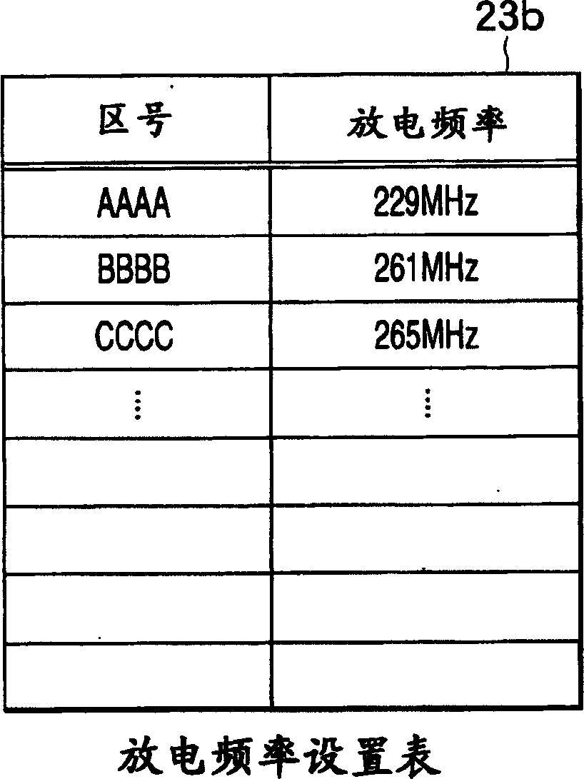
[0024] The ROM 23 stores the channel setting table 23a and the discharge frequency setting table 23b in a specific storage area.

[0025] figure 2 is a ...

no. 2 example

[0043] Next, a second embodiment of the present invention will be described.

[0044] Assume the discharge frequency is 261kHz. Among the high-order harmonic frequencies of the discharge frequency, there are the following four frequencies in the AM radio band: 783, 1044, 1305, and 1566KHz. All of these frequencies are multiples of 9 and coincide with AM radio frequencies. However, there are currently no AM stations using these 4 frequencies in Japan. That said, setting the discharge frequency to 261 minimizes interference with AM stations in Japan. The same is true for other countries in the world.

no. 3 example

[0046] Next, a third embodiment of the present invention will be described.

[0047] In the third embodiment, the discharge frequency of the display electrodes 4 is designed to be changeable to one of a plurality of switching values. In the third embodiment, two fixed values ​​of 230 kHz and 260 kHz are regarded as conversion values. The discharge frequency is converted by the control part 24 according to the instruction given by the user.

[0048] The number of AM stations that can be received in each area is not very large. If the discharge frequency is 230kHz, the higher harmonic frequencies in the AM radio band are 690, 920, 1150, and 1380kHz. If the discharge frequency is 260kHz, the higher harmonic frequencies in the AM radio band are 780, 1040, 1300, and 1560kHz.

[0049] For example, assume that interference with an AM station occurs when the discharge frequency is 230kHz. In this case, when the discharge frequency is converted to 260kHz, the higher harmonics are s...


PUM


Abstract

An image display apparatus with discharge devices comprises a display section (26) which displays an image by causing phosphors to emit light by the discharge energy of the discharge devices, and a discharge frequency control section (24) which controls the discharge frequency of the discharge devices so as to prevent the discharge frequency and its integral-degree harmonic frequencies from coinciding with a public broadcasting frequency in an area where the apparatus is installed.

Description

technical field [0001] The present invention relates to an image display device that displays moving images, still images, or symbol codes (hereinafter collectively referred to as images). In particular, the present invention relates to an image display device using a discharge device, such as a flat panel display device. Background technique [0002] A flat panel display device, such as a plasma display (PDP), has a discharge device composed of pixels one by one. The discharge device discharges when a voltage of up to 200V is applied to the discharge device. Ultraviolet rays generated by the discharge energy irradiate the fluorescent substance. As a result, the pixels glow and the image is displayed. When the PDP is driven, the discharge frequency is constant. The discharge frequency value is determined by the manufacturer according to the performance of the display panel, the performance of the control circuit and other factors. [0003] It is well known that the nois...

Claims


Application Information

Patent Timeline
Patent Type & Authority Applications(China)
IPC IPC(8): H04N5/66G09G3/20G09G3/28G09G3/288G09G3/291G09G3/294G09G3/296G09G3/298
CPCG09G2330/06G09G3/291
Inventor 都築吉司
Owner KK TOSHIBA
Why Eureka
Try Eureka