Redundant switching controlling method and circuit

A control method and redundant switching technology, which are applied in the detection of faulty computer hardware, logic operation inspection, etc., can solve the problems of not determining the logic state according to the degree of failure, the determination of the logic state is long, and the determination of the logic state is not involved. The effect of low cost and simple logic circuit

Inactive Publication Date: 2005-03-09
ZHEJIANG SUPCON TECH +1
View PDF1 Cites 17 Cited by
  • Summary
  • Abstract
  • Description
  • Claims
  • Application Information

AI Technical Summary

Problems solved by technology

[0008] 1. When two logical objects that are mutually redundant are powered on at the same time, it takes a long time to determine the logical state;
[0009] 2. Failure to perform redundant switching under failure conditions according to the degree of failure;
[0010] 3. Manual redundancy switching is not implemented;
[0011] 4. Does not involve the determination of the logic state in the case of power-off and reset of the logic object in positive logic

Method used


Image

  • Redundant switching controlling method and circuit
  • Redundant switching controlling method and circuit
  • Redundant switching controlling method and circuit

Examples


Embodiment Construction

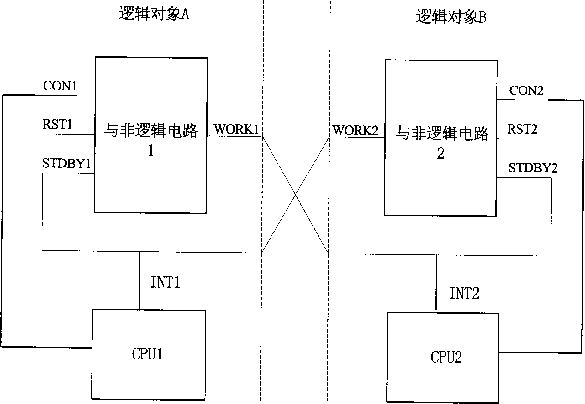
[0076] Please refer to figure 1 Shown is a schematic diagram of the redundant switching control circuit of the present invention. The logic circuit is mainly composed of a group of NAND logic circuits and a central processing unit, and realizes the exchange of logic state information of two logic objects A and B and the interlocking function of logic states. In this embodiment, two NAND logic circuits are used as a schematic illustration. The NAND logic circuits 1 and 2 correspond to logic objects A and B respectively, and have three input terminals. The first input terminals CON1 and CON2 transmit control signals, which are controlled by Central processing unit CPU1, CPU2 control; second input terminal RST1, RST2, transmit reset signal, controlled by the reset chip of logic object A, B, when logic object A, B is reset, the corresponding RST1, RST2 is low level.

[0077] The third input terminal STDBY1 of the non-logic circuit 1 transmits a state signal, and is connected with...


PUM


Abstract

The present invention relates to a redundancy switching control method and its circuit. Said method includes the following steps: detecting that logical object A of positive logic state produces abnormal state and notifying it to another logical object B; according to the failure extent of self-body another logical object B can define logical state; according to the logical state of logical object B logical object A can make failure extent comparison, and again define logical state of self-body; according to the requirement repeating the above-mentioned steps until the logical object with lighter failure extent can be defined into positive logical state. The correspondent control circuit includes a group of AND-NOT circuits and processor, said AND-NOT circuits are respectively correspondent to logical objects, have three input ends; first input end is used for transferring control signal; second input end is used for transferring reset signal; and third input end is used for transferring state signal, and is connected with output end of relative logical object and illogical circuit.

Description

technical field [0001] The invention relates to the switch in the redundant system in the automatic control field, especially the control method and the circuit in the redundant switch. Background technique [0002] Generally speaking, in the field of industrial automation, redundant configuration is performed on the main control module or important analog input and output modules to reduce the risk of failure and increase the reliability of the system. Typically, these modules (ie, logical objects) employ more than one central processing unit (CPU). In this way, when the abnormal state of the logic object occurs, if necessary, the positive and negative logic state can be switched under the control of the central processing unit to ensure the continuity of the control task. [0003] Usually, when constructing a redundant system of two main control modules or input / output (I / O) modules in a distributed control system (DCS), it is necessary to control the redundancy switching...

Claims


Application Information

Patent Timeline
Patent Type & Authority Applications(China)
IPC IPC(8): G06F11/22G06F11/25
Inventor 李华军黄文君金建祥靳旭哲
Owner ZHEJIANG SUPCON TECH
Why Eureka
Try Eureka