Supercharge Your Innovation With Domain-Expert AI Agents!

Fuel supply device for motor-driven two-wheeled vehicle

A fuel supply device and a technology for motorized two-wheeled vehicles, which are applied to the layout combined with the fuel supply of internal combustion engines, power devices, liquid fuel feeders, etc., can solve the problems of complicated structures and increased number of parts, and achieve miniaturization Effect

Inactive Publication Date: 2005-03-16
HONDA MOTOR CO LTD
View PDF3 Cites 2 Cited by
  • Summary
  • Abstract
  • Description
  • Claims
  • Application Information

AI Technical Summary

Problems solved by technology

In this way, the number of parts increases and the structure is complicated in both the box type and the series type.

Method used


Image

  • Fuel supply device for motor-driven two-wheeled vehicle
  • Fuel supply device for motor-driven two-wheeled vehicle
  • Fuel supply device for motor-driven two-wheeled vehicle

Examples


Embodiment Construction

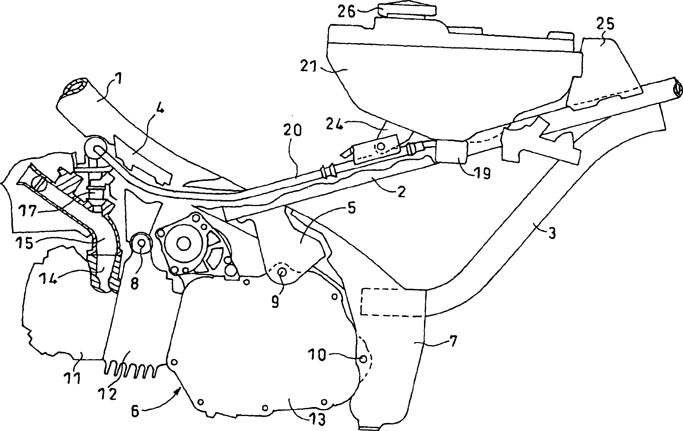
[0023] Next, an embodiment of the present invention will be described with reference to the drawings. figure 2 It is an exploded side view of essential parts of a motorcycle equipped with a fuel supply device according to an embodiment of the present invention. The frame of a motorcycle consists of a main frame 1 that connects the front end to a head pipe (not shown) located at the front of the vehicle body (left side in the figure), an upper rear frame 2 extending obliquely rearward from the main frame 1, and a lower rear frame. Framework 3 constitutes. The upper rear frame 2 is joined to the main frame 1 by brackets 5 and the lower rear frame 3 is joined to the main frame 1 by brackets 7 . The upper rear frame 2 and the lower rear frame 3 are joined to each other at a position close to the rear of the vehicle body.

[0024] An engine 6 is disposed below the main frame 1 . Engine 6 is suspended by brackets 4, 5 and bracket 7 at the lower part of main frame 1 . The engine...


PUM


Abstract

To simplify the construction of a fuel feeder. This fuel feeder feeds fuel from the fuel tank 21 to the fuel injection valve 17. The fuel pump 19 is mounted on the external surface of the fuel tank 21 bottom with the fuel suction port 381 facing the inside of the fuel tank 21. The fuel suction port 381 may be made to face the inside of the fuel tank 21 from the bottom side surface of the fuel tank 21. To minimize the rest of the fuel, there is provided a fuel pocket 215 swelled downward from the fuel tank 21 bottom. The external wall surface of the fuel pocket 215 is mounted with the fuel pump 19. The fuel pump 19 is a brushless motor includes the rotor 32 with a magnet connected to the impeller 37 and the stator coil 30 which is at such a position as to face the magnet 31 and is outside a housing 29.

Description

[0001] The present invention application is a divisional application of the invention application with the filing date of October 16, 2002 and the application number of 02146870.2. technical field [0002] The present invention relates to a fuel supply device for a motorcycle, and more particularly to a fuel supply device for a motorcycle that supplies fuel from a fuel tank to a fuel injection device. Background technique [0003] Fuel pumps for supplying fuel from a fuel tank to the fuel injection device are provided at various positions. As an in-tank type in which a fuel pump is arranged inside a fuel tank, the proposals described in JP-A-5-34265 and JP-A-1-257686 are known. In the former case, the pump device is inserted from above the fuel tank and fixed into the fuel tank. In the latter case, the pump device is inserted from the bottom surface of the fuel tank and fixed into the fuel tank. In addition, as a tandem type in which a fuel pump is arranged at a position s...

Claims


Application Information

Patent Timeline
Patent Type & Authority Applications(China)
IPC IPC(8): B62J35/00B60K15/00B60K15/077B62J37/00F02M37/00F02M37/08F02M37/10F02M37/20
CPCY02T10/123Y02T10/12
Inventor 中川光雄引地东一郎
Owner HONDA MOTOR CO LTD
Features
  • R&D
  • Intellectual Property
  • Life Sciences
  • Materials
  • Tech Scout
  • Unparalleled Data Quality
  • Higher Quality Content
  • 60% Fewer Hallucinations
Learn More