Check patentability & draft patents in minutes with Patsnap Eureka AI!

Immersion type membrane separator

A separation device, immersed membrane technology, applied in semi-permeable membrane separation, membrane, membrane technology and other directions, can solve problems such as wear and tear

Active Publication Date: 2013-05-22
KUBOTA LTD
View PDF1 Cites 0 Cited by
  • Summary
  • Abstract
  • Description
  • Claims
  • Application Information

AI Technical Summary

Problems solved by technology

[0006] However, since there is a gap between the upper end of the membrane cartridge 3 and the pressure plate 5, there is a problem that the upper end of the membrane cartridge 3 contacts the pressure plate 5 due to the upflow 17, the membrane cartridge 3 vibrates slightly, and the The upper end is repeatedly contacted with the pressure plate 5 to wear

Method used


Image

  • Immersion type membrane separator
  • Immersion type membrane separator
  • Immersion type membrane separator

Examples


Embodiment Construction

[0059] The following is the reference figure 1 ˜ FIG. 9 describe the first embodiment of the present invention.

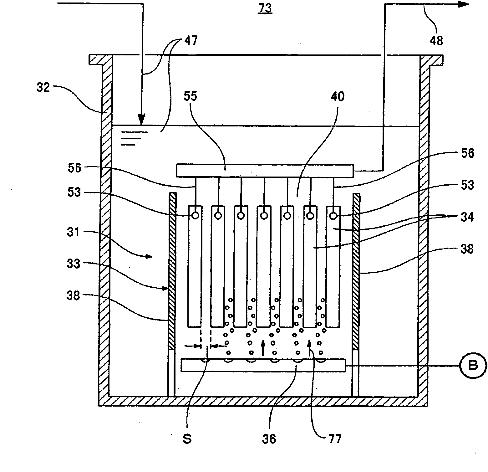
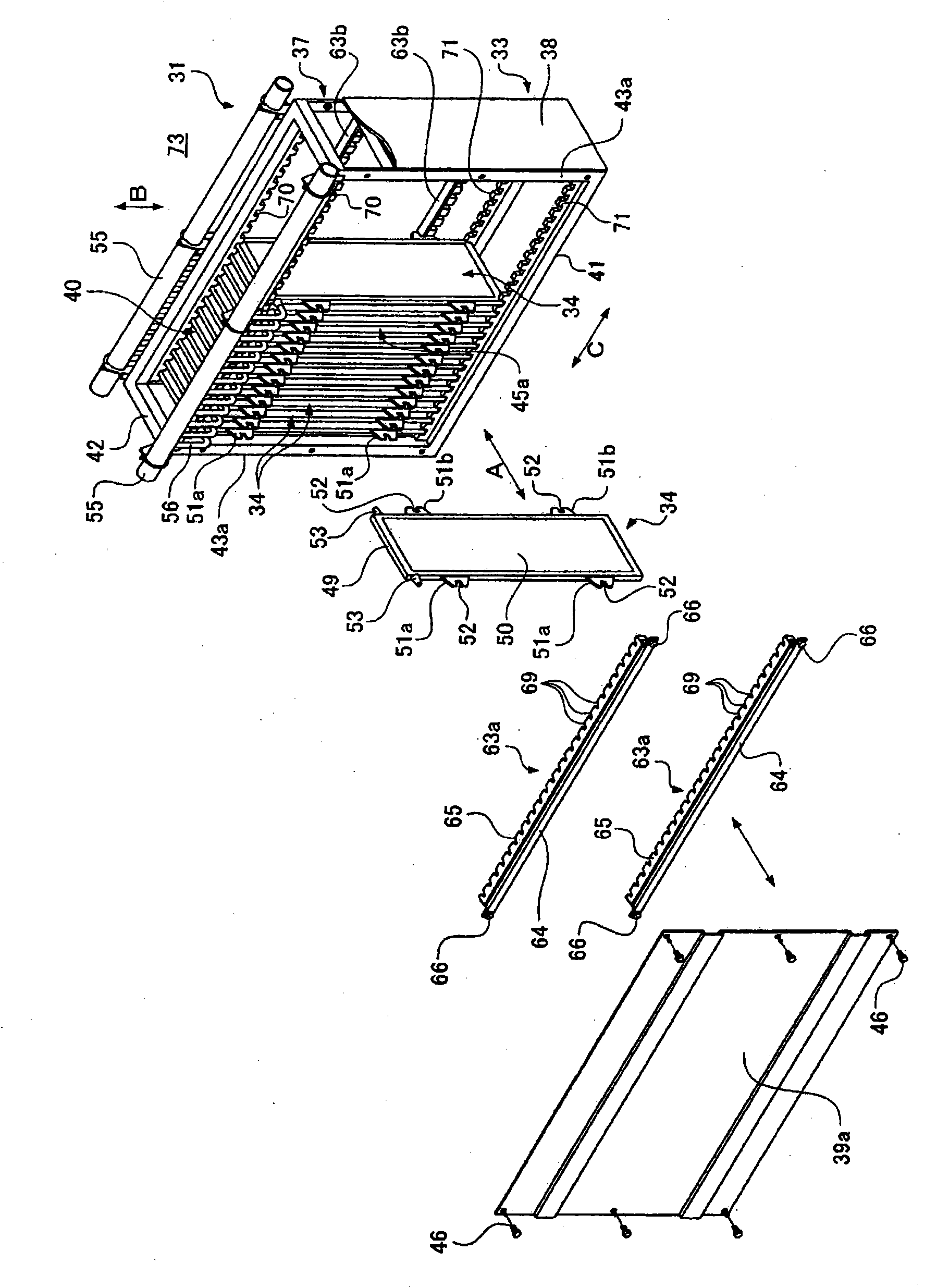
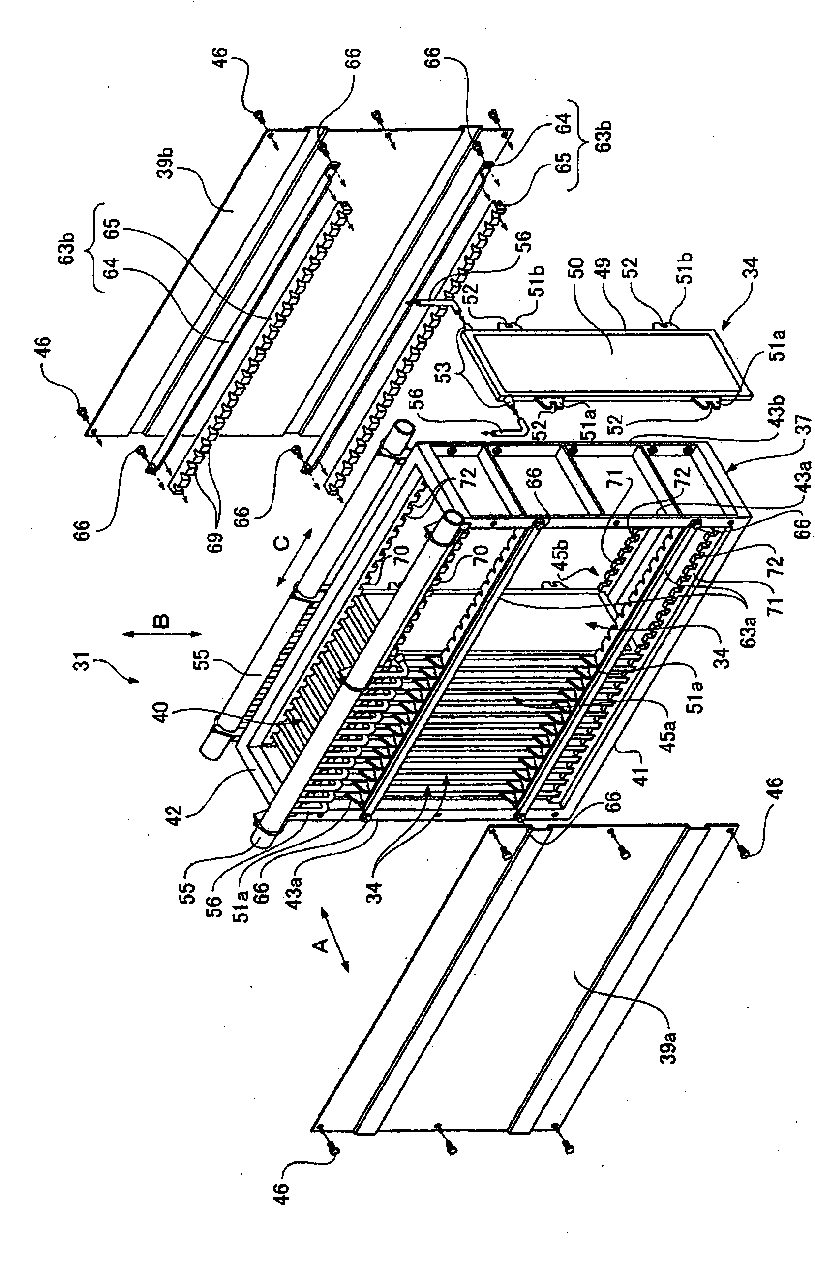
[0060] Such as figure 1 As shown, 31 is a submerged membrane separation device. This submerged membrane separation device 31 is submerged in the treatment tank 32 and separates raw water and treated water including activated sludge. The submerged membrane separation device 31 has a box-shaped membrane casing 33 with upper and lower openings, a plurality of flat-shaped membrane cartridges 34 and an air diffusion device 36; the membrane cartridges 34 are parallel to each other inside the membrane casing 33. Arranged so that the above-mentioned air diffuser 36 is arranged below these membrane filter elements 34 .

[0061] In addition, the air diffuser 36 is an example of a flow generating device, and generates an upward flow 77 along the membrane surface of the membrane cartridge 34 by jetting air from a plurality of discharge holes formed in the air diffuser pip...


PUM


Abstract

A submerged membrane separator 31 includes: a casing 33 opened at the top; a plurality of flat membrane cartridges 34 arrayed at intervals in the casing 33; and an air diffuser 36 provided below the membrane cartridges 34. The membrane cartridges 34 are movably held in the up-down direction in the casing 33 while having a space ± in the up-down direction. Lifting suppressing members 63a and 63b for restricting a lifting amount of the membrane cartridges 34 during filtration operation to be smaller than the space ± in the up-down direction are provided in the casing 33.

Description

technical field [0001] The present invention relates to a submerged membrane separation device submerged in liquid to be treated such as activated sludge mixed liquid in a treatment tank. Background technique [0002] Such as Figure 21 As shown, conventionally, as such a submerged membrane separation device 1 , there is a device that is submerged in a treatment tank and separates activated sludge and treated water. The submerged membrane separation device 1 has a box-shaped casing 2 opened up and down, a plurality of membrane cartridges 3 arranged in parallel to each other inside the casing 2 , and an air diffuser 4 provided below the membrane cartridges 3 . [0003] The membrane filter element 3 has a filter plate 12 and filter membranes 13 mounted on both sides of the filter plate 12 . Moreover, the air diffuser 4 is comprised so that air may be blown out from an air diffuser pipe. In addition, a pressure plate 5 for preventing the membrane filter element 3 from floatin...

Claims


Application Information

Patent Timeline
Patent Type & Authority Patents(China)
IPC IPC(8): B01D63/08C02F1/44
CPCB01D2315/06C02F3/1273B01D65/08B01D2321/185B01D63/08B01D61/18B01D63/082B01D2321/2058B01D2313/02B01D2313/06Y02W10/10B01D63/0821
Inventor 松崎好男上岛达也佐佐木智彦石川公博
Owner KUBOTA LTD
Features
  • R&D
  • Intellectual Property
  • Life Sciences
  • Materials
  • Tech Scout
  • Unparalleled Data Quality
  • Higher Quality Content
  • 60% Fewer Hallucinations
Learn More