Apparatus for applying spin to optical fiber and optical fiber manufacturing method and apparatus

An optical fiber and coating device technology, applied in the field of manufacturing an optical fiber, can solve the problems of different overall structure and failure to propose positional relationship, etc.

Inactive Publication Date: 2005-03-23
LG CABLE INC
View PDF9 Cites 17 Cited by
  • Summary
  • Abstract
  • Description
  • Claims
  • Application Information

AI Technical Summary

Problems solved by technology

However, these conventional techniques also failed to propose or suggest the positional relationship between the support roller and the guide roller for controlling the rotation rate, and the overall structure of the mechanism for providing a torque to the optical fiber and the rotation applying device is different from that of the present invention.

Method used


Image

  • Apparatus for applying spin to optical fiber and optical fiber manufacturing method and apparatus
  • Apparatus for applying spin to optical fiber and optical fiber manufacturing method and apparatus
  • Apparatus for applying spin to optical fiber and optical fiber manufacturing method and apparatus

Examples


Embodiment Construction

[0051] Hereinafter, preferred embodiments of the present invention will be described in detail with reference to the accompanying drawings.

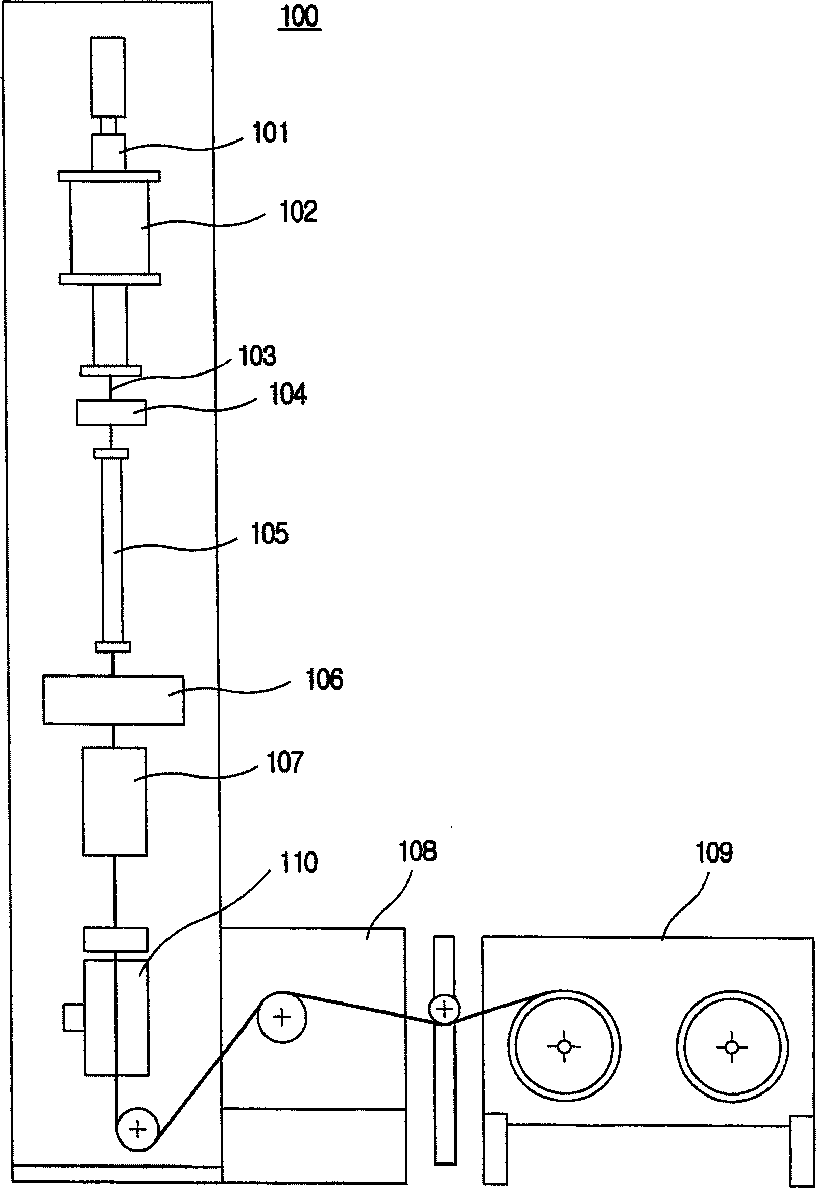
[0052] image 3 A schematic structural view of an optical fiber manufacturing device 100 according to the present invention is shown.

[0053] The optical fiber manufacturing apparatus 100 heats an optical fiber preform 101 to a high temperature in a furnace 102, and then draws a bare optical fiber 103 from the softened preform neck. The drawn bare optical fiber 103 passes through a peripheral measuring device 104 and is cooled in a cooling device 105, and then is coated with an ultraviolet curable resin at least once in a coating device 106. The optical fiber coated in the coating device 106 is then hardened in the hardening device 107 and then transported to the spin application device 110 .

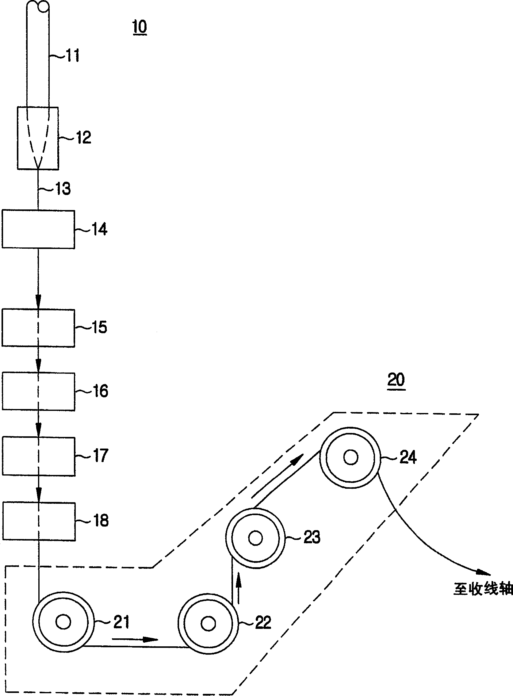
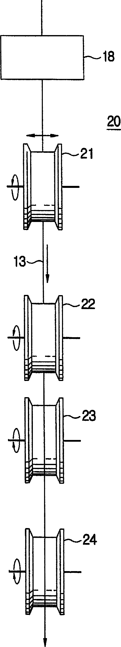
[0054] The fiber is twisted at a predetermined rotation rate in the rotation applying device 110 and then travels to the take-up device (ie, a...


PUM


Abstract

A method of applying spin to a coated optical fiber to be rotated on its longitudinal axis so that the optical fiber has an ultra-low PMD (Polarization Mode Dispersion) includes the steps of: guiding the coated optical fiber so as not to be deviated from a certain range off a drawing axis at a lower end of an optical fiber coating point; giving torque to the optical fiber by contacting the coated optical fiber with a driving roller which vibrates on the center of an axis substantially parallel to a drawing direction at a lower end of the guiding point; and adjusting an amplitude (A) of the driving roller and a distance (l) between the guiding point and the vibrating point so as to control an angle (Theta) between the vibrating optical and the drawing axis. This makes it possible to control a spin rate (spins / m) of the optical fiber generated by rotation.

Description

technical field [0001] The present invention relates to the manufacture of an optical fiber, in particular to a method and apparatus for imparting spin to an optical fiber to manufacture an optical fiber with ultra-low polarization mode dispersion (PMD). Background technique [0002] A single-mode fiber with a circular symmetric structure theoretically has two orthogonal polarization modes that are independent and complementary to each other. In general, the electric field of light propagating through an optical fiber can be considered as a linear superposition of these two special polarization modes. In fact in single-mode fibers, compensation of the two polarization modes occurs due to imperfections such as symmetric transverse stress or eccentricity of the circular core. These two modes propagate at different phase velocities, so the two modes have different propagation constants (β 1 and beta 2 ). The difference in the propagation constant is called the double fracti...

Claims


Application Information

Patent Timeline
Patent Type & Authority Applications(China)
IPC IPC(8): G02B6/00C03B37/027C03B37/03C03B37/12
CPCC03B2205/06C03B37/02745C03B2203/19C03B37/032C03B2203/36G02B6/00
Inventor 权宁一裵相俊李俊根张明浩李奉勋
Owner LG CABLE INC
Why Eureka
Try Eureka