Network load balancing with connection manipulation

A technology of connection state and network stack, applied in the direction of data exchange network, data exchange through path configuration, digital transmission system, etc., can solve the problem of increasing hardware capabilities

Active Publication Date: 2005-04-20
MICROSOFT TECH LICENSING LLC
View PDF1 Cites 29 Cited by
  • Summary
  • Abstract
  • Description
  • Claims
  • Application Information

AI Technical Summary

Problems solved by technology

This scaling up of the performance of the load balancing operation is therefore limited to the ability to increase the hardware by its replacement

Method used


Image

  • Network load balancing with connection manipulation
  • Network load balancing with connection manipulation
  • Network load balancing with connection manipulation

Examples


Embodiment Construction

[0062] Sample Network Load Balancing Example

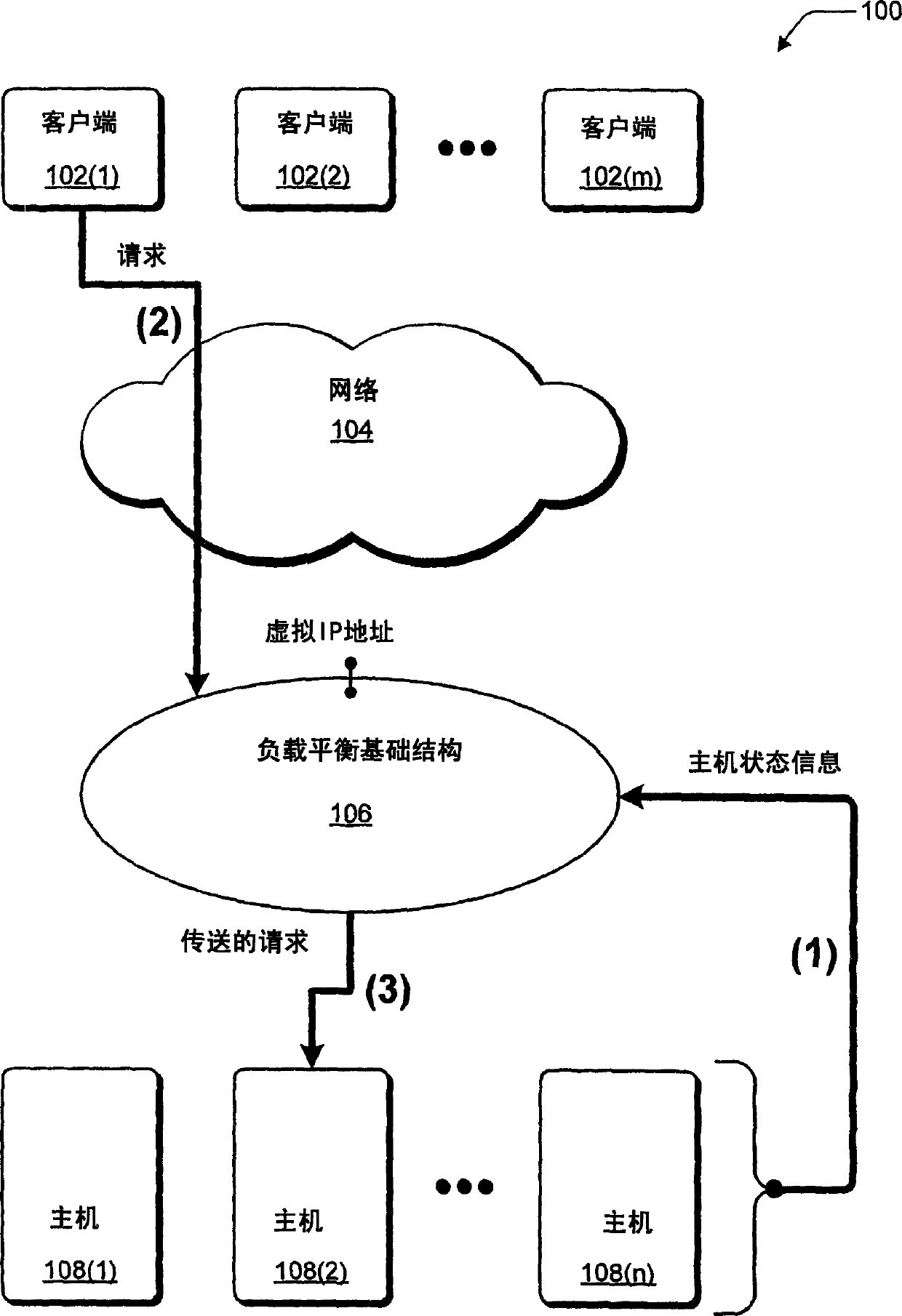
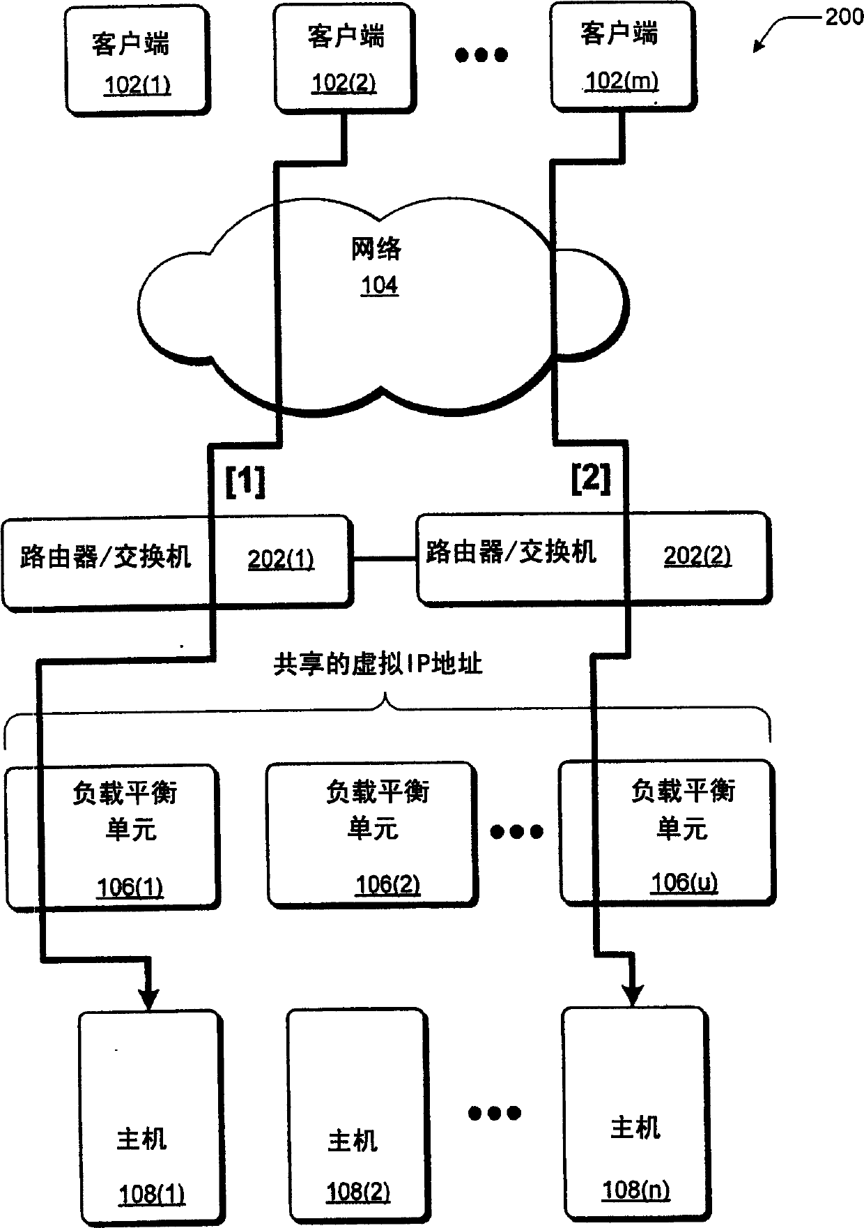
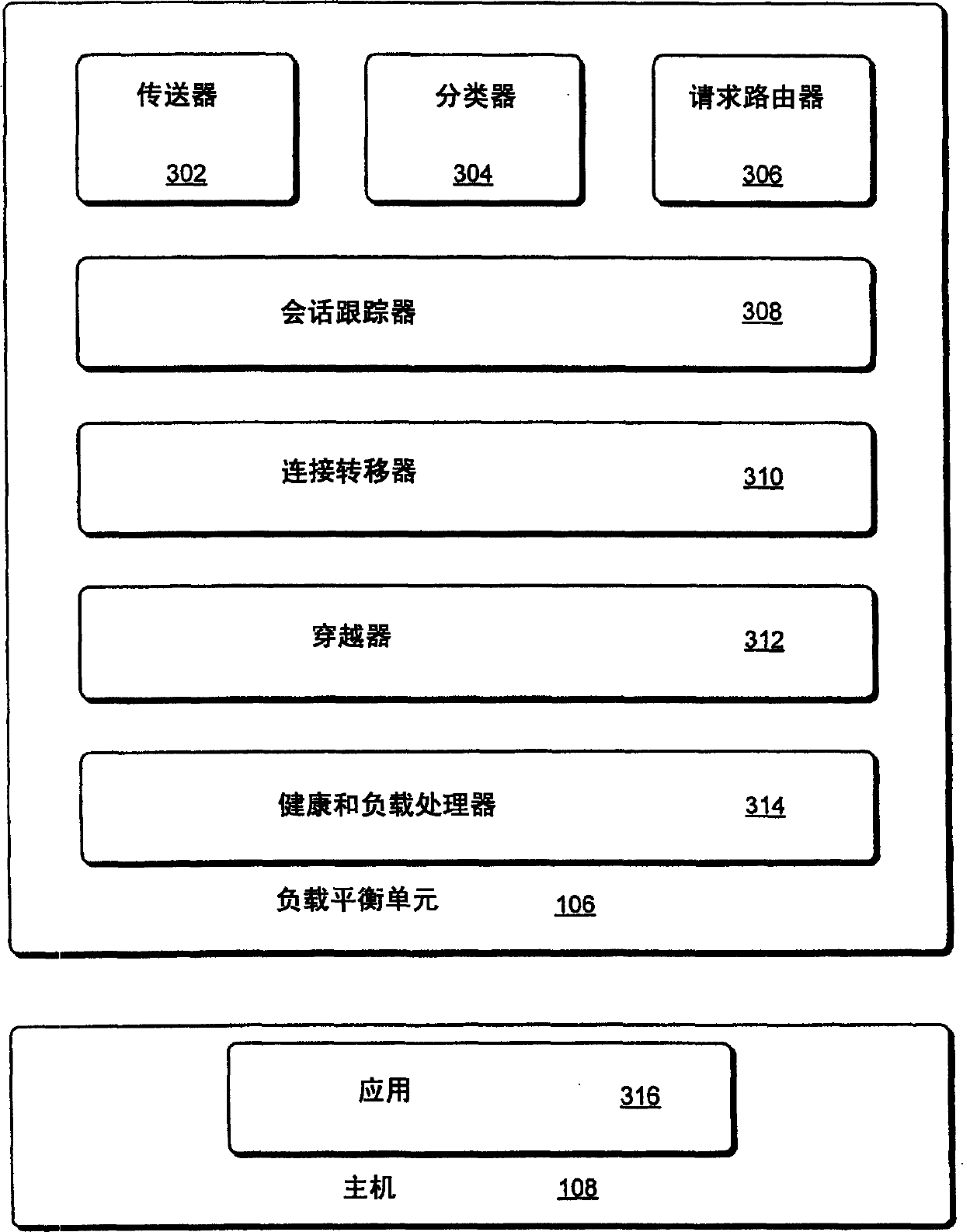
[0063] This section describes an example paradigm of network load balancing and is used to provide the basis, environment, context, etc. for the descriptions of the following sections. This part mainly refers to Figure 1-3.

[0064] FIG. 1 is an example network load balancing paradigm 100 showing a load balancing infrastructure 106 and multiple hosts 108 . The exemplary network load balancing paradigm 100 includes a plurality of clients 102(1), 102(2)...102(m) and a plurality of hosts 108(1), 108(2)...108(n) and a network 104 and load balancing infrastructure 106.

[0065] Each client 102 may be any device capable of network communication, such as a computer, mobile station, entertainment device, another network, and the like. Client 102 may also be associated with a person and / or entity operating a client device. In other words, clients 102 include logical clients that are users and / or machines. Network 104 may consist of on...


PUM


Abstract

In an exemplary device implementation, a device includes: a connection migrator that is configured to migrate connections away from the device; the connection migrator capable of precipitating a compilation of protocol state for a connection across a protocol stack; the connection migrator adapted to aggregate the compiled protocol state with data for the connection into an aggregated connection state; the connection migrator further capable of causing the aggregated connection state to be sent toward a target device. In an exemplary media implementation, processor-executable instructions direct a device to perform actions including: obtaining at least a portion of a source / destination pair from a packet; accessing an encapsulation mapping table using the at least a portion of the source / destination pair to locate an encapsulation mapping entry; extracting a flow identifier from the encapsulation mapping entry; and replacing part of the packet with the flow identifier to produce an encapsulated packet.

Description

[0001] Related Patent Applications [0002] This U.S. nonprovisional patent application is a continuation-in-part of (i) co-pending U.S. nonprovisional patent application Serial No. 10 / 610506 (filed June 30, 2003), (ii) co-pending U.S. nonprovisional patent Continuation-in-Part of Application Serial No. 10 / 610519 (filed June 30, 2003), and (iii) co-pending U.S. Nonprovisional Patent Application Serial No. 10 / 610321 (filed June 30, 2003) Continue to apply in part. [0003] Specifically, this U.S. non-provisional patent application is a continuation-in-part of co-pending U.S. non-provisional patent application Serial No. 10 / 610,506, filed June 30, 2003, entitled "FlexibleNetwork Load Balancing," and is incorporated by reference The whole unites here. [0004] Specifically, this U.S. nonprovisional patent application is also a continuation-in-part of co-pending U.S. nonprovisional patent application Serial No. 10 / 610519, filed June 30, 2003, entitled "NetworkLoad Balancing with H...

Claims


Application Information

Patent Timeline
Patent Type & Authority Applications(China)
IPC IPC(8): H04L12/56G06F15/16H04L29/06H04L29/08H04L29/12
CPCH04L61/2557H04L67/1008H04L67/1027H04L67/1029H04L67/101H04L67/1034H04L67/14H04L67/02H04L67/142H04L67/1014H04L67/1017H04L67/1023H04L69/329H04L61/00H04L67/1001H04L67/564H04L67/63G06F15/16H04L9/40
Inventor A·贝德格辛S·B·豪斯A·海德J·M·周S·N·堪尼亚R·V·韦尔兰德
Owner MICROSOFT TECH LICENSING LLC
Why Eureka
Try Eureka