Supercharge Your Innovation With Domain-Expert AI Agents!

Aligning device for an injection nozzle

An injection nozzle and aligning device technology, applied in the field of injection molding machines, can solve the problems of not easy installation/removal of fixtures, complex and expensive fixture structures, etc.

Inactive Publication Date: 2005-05-04
FANUC LTD
View PDF2 Cites 2 Cited by
  • Summary
  • Abstract
  • Description
  • Claims
  • Application Information

AI Technical Summary

Problems solved by technology

Also, the jig used includes a sensor, etc., so that the structure of the jig becomes complicated and expensive, and the installation / removal of the jig is not easy

Method used


Image

  • Aligning device for an injection nozzle
  • Aligning device for an injection nozzle
  • Aligning device for an injection nozzle

Examples


Embodiment Construction

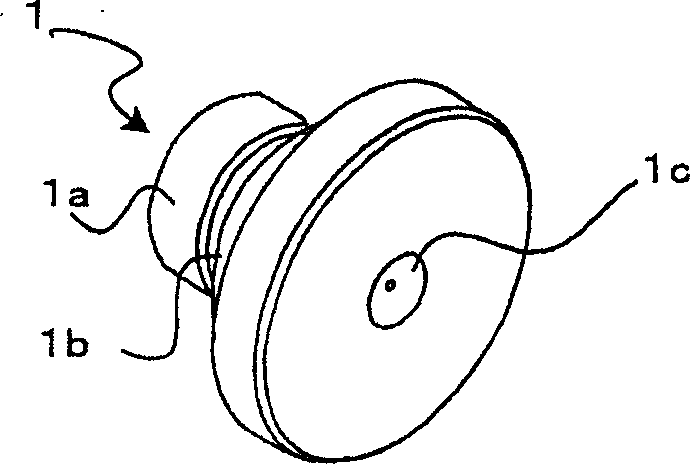
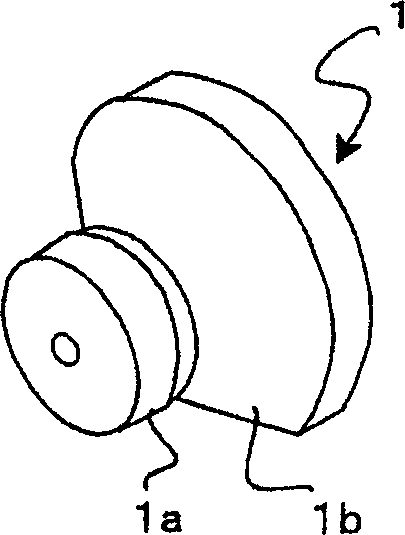
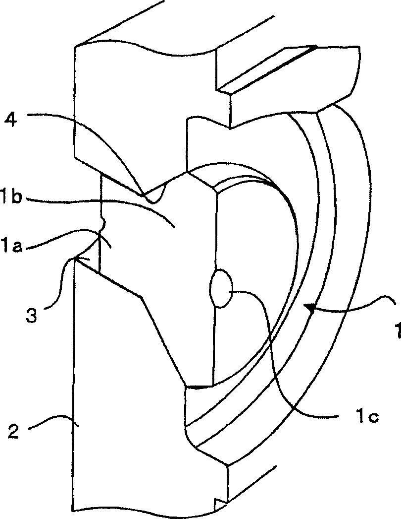
[0023] Figure 1a and 1b It is a perspective view of the alignment jig including the injection nozzle alignment device shown from different directions in the first embodiment of the present invention. The alignment jig 1 has a cylindrical portion 1a and a conical portion 1b coaxial with the cylindrical portion 1a and continuing from the cylindrical portion 1a, the conical portion 1b has a bottom surface (end facing the cylindrical portion) and A recess 1c is formed at the center of the bottom surface (on the axis of the cylindrical portion 1a and the conical portion 1b) and engages with the distal end of the injection nozzle. The recess 1c has a concave surface matched to the distal end of the injection nozzle so as to be in close contact with the distal end, and the size of the concave surface is slightly larger than that of the distal end of the injection nozzle.

[0024] On the other hand, the fixed platen 2 connected to the fixed mold half has a mounting hole for receivi...


PUM


Abstract

An aligning device whereby an injection nozzle can be easily aligned with the sprue of a mold. A stationary platen has a locating hole formed therein and a tapered portion continuous with the locating hole and tapered in a direction such that the tapered portion broadens toward the injection nozzle side. An aligning jig to be fitted into the locating hole and the tapered portion is prepared. The jig has a recess formed in the center of an end face thereof and having a shape matching that of the distal end of the injection nozzle. The jig is fitted into the locating hole, and the injection nozzle is engaged with the recess to align the injection nozzle with the axis of the locating hole. Since the mold is attached to the stationary platen such that the axis of the sprue of the mold is aligned with that of the locating hole, the injection nozzle becomes aligned with the sprue. The injection nozzle can be easily and accurately aligned even while the mold is attached to the stationary platen and also the mold and the injection cylinder are heated to high temperature.

Description

technical field [0001] The invention relates to an injection molding machine, in particular to an alignment device for aligning the axis of an injection nozzle with the axis of a mold injection port. Background technique [0002] In an injection molding machine, the mold is closed by the movable half of the mold attached to the movable platen coming into contact with the fixed half of the mold attached to the fixed platen, and the molten resin in the injection cylinder is injected from the injection nozzle into the mold. It is therefore necessary to align the axis of the injection nozzle with the axis of the injection port of the mold. [0003] By convention, such as Figure 7 As shown, a peep hole 20 extending obliquely relative to the axis of the injection nozzle is formed through the fixed platen 2 near the positioning hole, so that the contact between the distal end of the injection nozzle and the injection port sleeve of the mold can be seen through the peep hole. Obs...

Claims


Application Information

Patent Timeline
Patent Type & Authority Applications(China)
IPC IPC(8): B22D17/20B29C45/17B29C45/20
CPCB29C45/1781
Inventor 吉冈光志川崎达也
Owner FANUC LTD
Features
  • R&D
  • Intellectual Property
  • Life Sciences
  • Materials
  • Tech Scout
  • Unparalleled Data Quality
  • Higher Quality Content
  • 60% Fewer Hallucinations
Learn More