Biosensor and measuring apparatus for biosensor

a biosensor and measuring apparatus technology, applied in the field of biosensors and measuring apparatuses for biosensors, can solve the problems of inability to realize the measurement of biosensors, e.g. visual, inability to discriminate, etc., and achieve the effect of conventional biosensors or combinations

Active Publication Date: 2005-10-13
PHC HLDG CORP
View PDF7 Cites 34 Cited by
  • Summary
  • Abstract
  • Description
  • Claims
  • Application Information

AI Technical Summary

Benefits of technology

[0009] Thus, an object of the present invention is to provide a biosensor and a measuring apparatus for a biosensor, in which wrong insertion of the biosensor into the measuring apparatus by a user can be prevented.
[0010] Another object of the present invention is to provide a measuring apparatus for a biosensor, which apparatus can be handily used for measuring plural biosensors corresponding to plural targeted substrates without causing wrong insertion of the biosensors.

Problems solved by technology

Accordingly, it is difficult for a user to discriminate, e.g. visually, between the topside and downside of the biosensor.
Therefore, there is a possibility that the user may insert the biosensor upside down, making a mistake in the top-down side matching of the biosensor with respect to the apparatus.
With such wrong insertion of the biosensor, correct measurement cannot be expected.
However, it cannot be realized by a conventional biosensor or a combination of a conventional biosensor and a conventional measuring apparatus for a biosensor.

Method used


Image

  • Biosensor and measuring apparatus for biosensor
  • Biosensor and measuring apparatus for biosensor
  • Biosensor and measuring apparatus for biosensor

Examples


embodiment mode 1

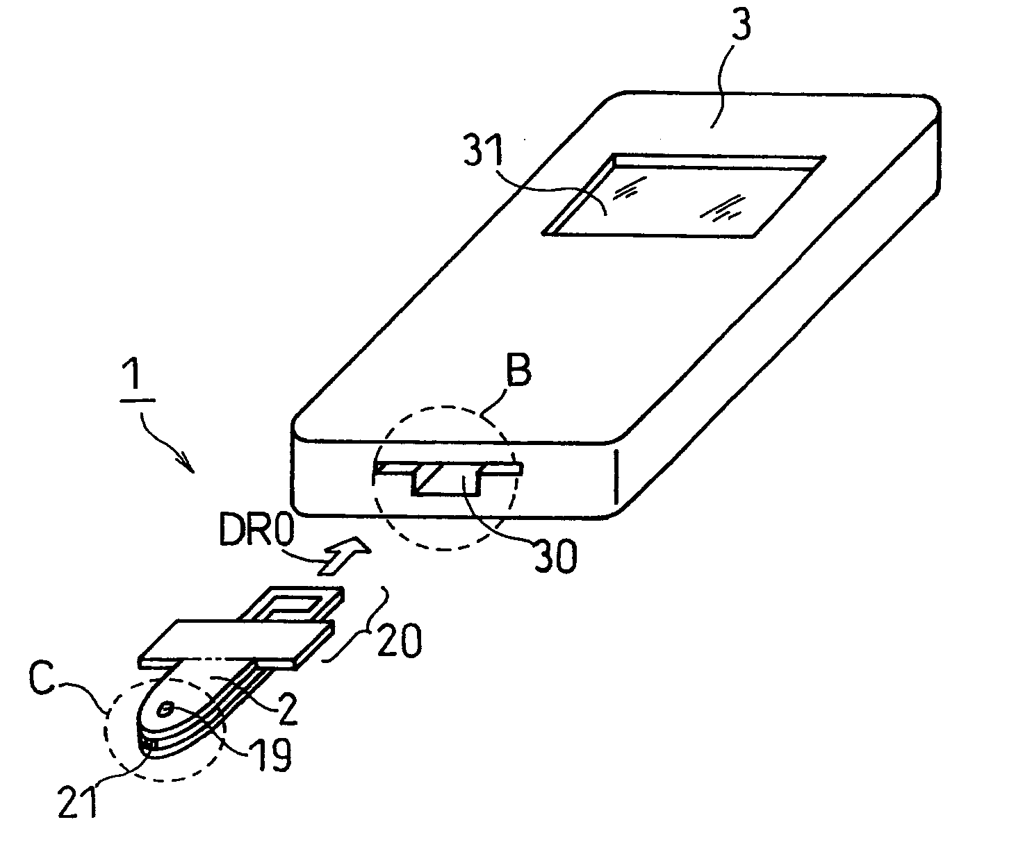
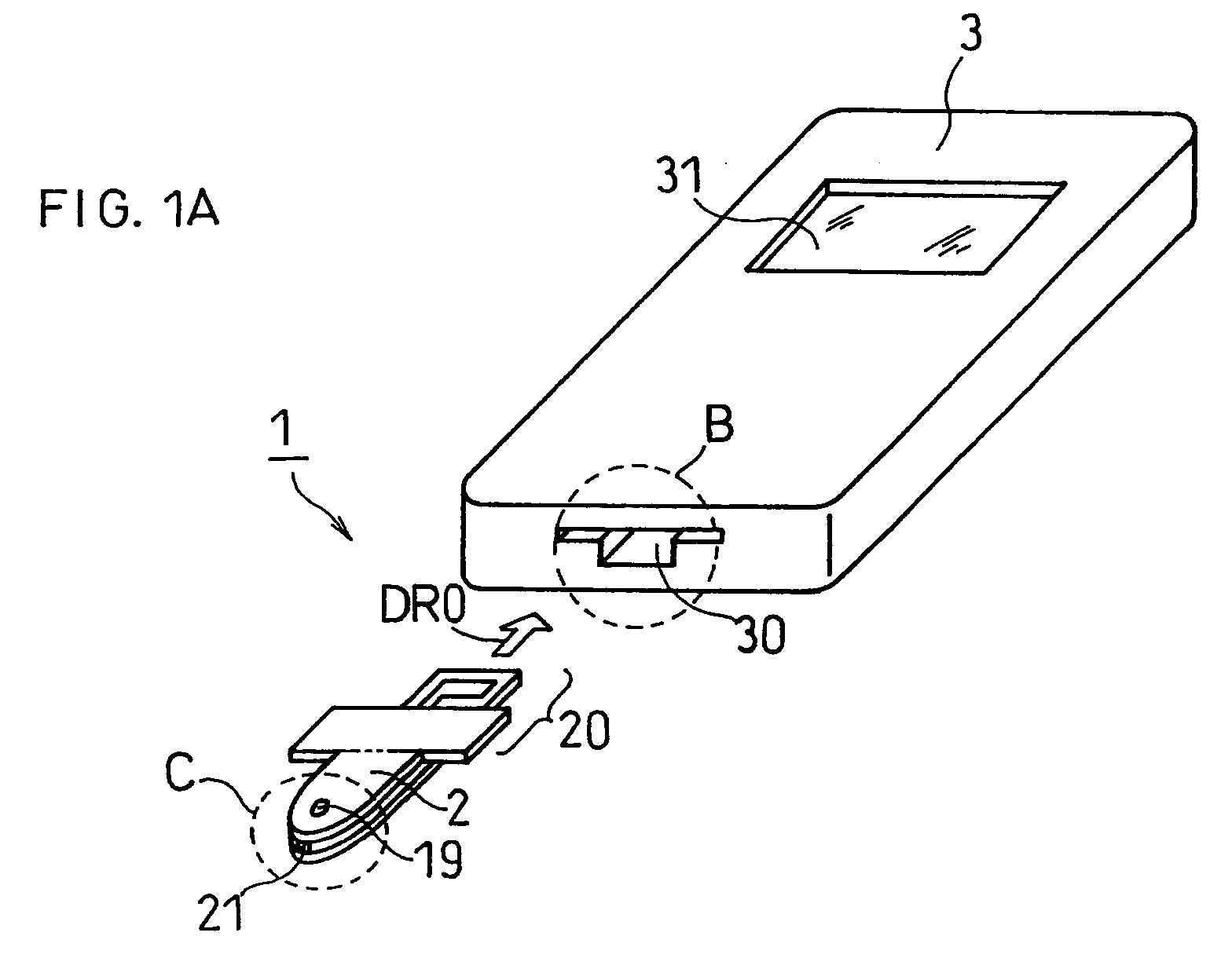
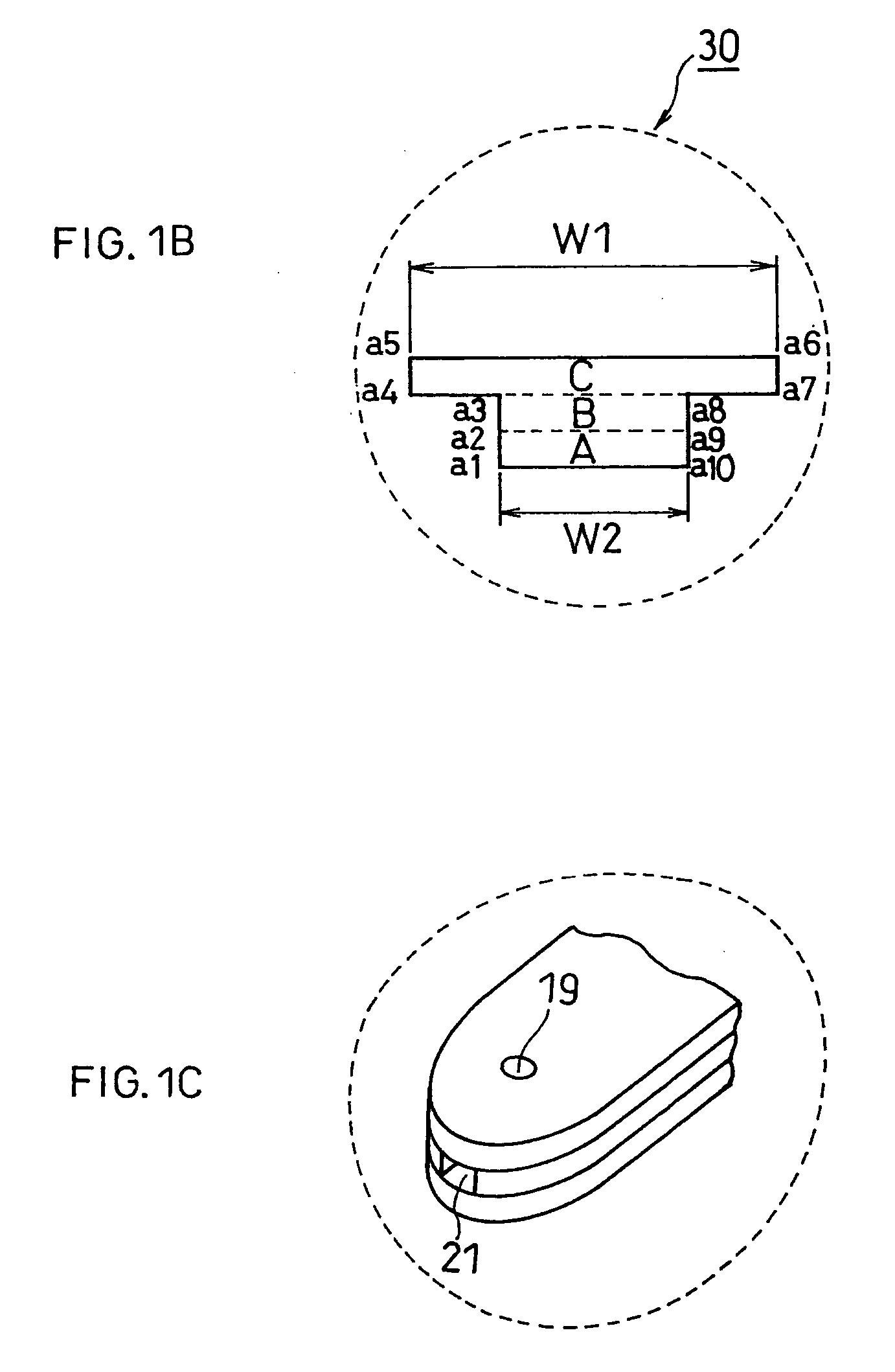
[0058]FIG. 1A is a schematic oblique view of a biosensor system 1 according to EMBODIMENT MODE 1 of the present invention, and FIG. 1B is a schematic view, partially enlarged, of a part in FIG. 1A as encircled by dashed line circle B, which is a sensor mounting portion 30 of a measuring apparatus 3 as seen in the arrow direction DR0. Further, FIG. 1C is a schematic oblique view, partially enlarged, of a part of FIG. 1A as encircled by dashed line circle C, which is an end portion of the biosensor 2. The biosensor system 1 comprises the biosensor 2 and the measuring apparatus 3 for measuring biosensors, particularly for having the biosensor 2 mounted therein.

[0059] Before describing details of respective elements of the biosensor system 1, the measuring operation using the biosensor system 1 is briefly described as follows. In the present specification, the term measuring operations is used to mean the operation of quantifying a substrate in a sample solution as well as the operatio...

embodiment mode 2

[0128] This EMBODIMENT MODE 2 is different from EMBODIMENT MODE 1 in that, in this EMBODIMENT MODE 2, plural different biosensors having different measurement targets are subjected to measurements by one measuring apparatus. In the following, description will be made with respect mainly to such different points.

[0129]FIG. 5A is a schematic oblique view of a biosensor system 4 according to the present EMBODIMENT MODE 2, while FIG. 5B is a schematic enlarged view of a portion encircled by dashed line circle B in FIG. 5A (namely, end face of sensor mounting portion 70 of measuring apparatus 7 as seen in arrow DR5 direction). The biosensor system 4 comprises a biosensor 5, a biosensor 6 and a measuring apparatus 7 (measuring apparatus for biosensor) in which each such biosensor is mounted for measuring operation. This biosensor system 4 is briefly described below.

[0130] The biosensor 5 is different from the biosensor 6 with respect to the measurement targets. More specifically, the ta...


PUM

PropertyMeasurementUnit
lengthaaaaaaaaaa
widthaaaaaaaaaa
shapeaaaaaaaaaa

Abstract

In biosensor system 1, biosensor 2 is mounted in measuring apparatus 3 for quantifying or detecting existence of a targeted substrate in a sample solution. Mounting end portion 20 of biosensor 2 to be mounted in measuring apparatus 3 has an extension of one base plate in the length direction, and further extensions of the other base plate in the width direction. Sensor mounting portion 30 of measuring apparatus 3 has a shape matching up with the shape of mounting end portion 20. Thereby wrong insertion of biosensor 2 in measuring apparatus 3 can be prevented. Further, varying shapes of plural biosensors 5 and 6 to have a common part and a non-common part, such biosensors can be handily measured by one measuring apparatus 7.

Description

BACKGROUND OF THE INVENTION [0001] The present invention relates to a biosensor and a measuring apparatus for a biosensor for quantifying and / or detecting existence of a substrate contained in a sample solution. [0002] A biosensor is such a sensor that uses, for a molecule discrimination device, fundamental biological elements such as microbes, enzymes, antibodies, DNAs (deoxyribonucleic acids) and RNAs (ribonucleic acids). More specifically, a biosensor can quantify or detect existence of a substrate contained in a sample solution by utilizing a reaction generated when a substrate is recognized or contacted by a fundamental biological element, for example, such reaction as oxygen consumption by microbial respiration, light emission or enzyme reaction. [0003] Among various biosensors, the commercialization of enzyme sensors, which quantify or detect existence of substrates by using an enzyme and reacting the enzyme with a targeted substrate, has been advanced. For example, enzyme se...

Claims


Application Information

Patent Timeline
Patent Type & Authority Applications(United States)
IPC IPC(8): A61B5/00G01N27/30G01N33/487
CPCA61B5/1486A61B2562/0295G01N33/4875G01N27/3273
Inventor TANIIKE, YUKOMIYASHITA, MARIKOIKEDA, SHINYOSHIOKA, TOSHIHIKOTOKUNO, YOSHINOBU
Owner PHC HLDG CORP
Why Eureka
Try Eureka