Shape matching cushion

a cushion and shape technology, applied in the field of support surfaces, can solve the problems of ischemic induced sores, extremely dangerous individuals confined to beds or wheelchairs, and difficult to treat and cur

Active Publication Date: 2008-09-16
ROHO
View PDF21 Cites 34 Cited by
  • Summary
  • Abstract
  • Description
  • Claims
  • Application Information

AI Technical Summary

Benefits of technology

[0005]One aspect of the invention provides for a cushion having an array of suspension elements. Each suspension element has a displaceable, load-bearing surface, a first end wall, a second end wall, and an optional bottom wall. The load bearing surface, end walls and bottom wall, if present, define an inner chamber. The material thickness of the load-bearing surface is greater than the material thickness of the end walls so that the end walls can distend outwardly when force is applied to said load-bearing surface. The optional bottom wall has a vent opening formed therein of a predetermined size that allows controlled release of air from the chamber when force is applied to the load bearing surface to control collapsing of the cell.
[0007]In one aspect of the invention the array of suspension elements is arranged in a pattern wherein the longitudinal axis of each suspension element is positioned at a right angle relationship to the longitudinal axis of the adjacent suspension elements. The right angle axis position of the suspension elements improves stability imparted to the user.

Problems solved by technology

Individuals confined to bed or to a wheelchair run the risk of tissue breakdown and the development of ischemic induced sores, which are extremely dangerous and difficult to treat and cure.
Any skin area where there are sustained deformation experiences reduced blood flow and the skin does not receive sufficient oxygen and nutrients.

Method used


Image

  • Shape matching cushion
  • Shape matching cushion
  • Shape matching cushion

Examples


Embodiment Construction

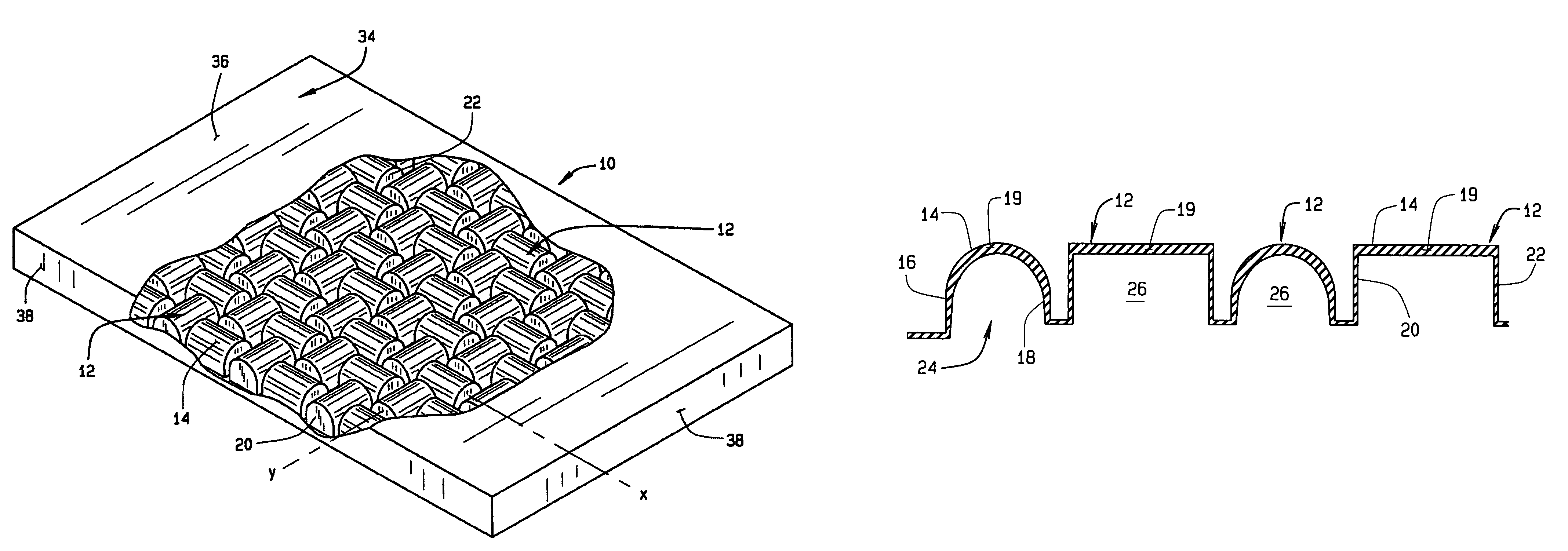
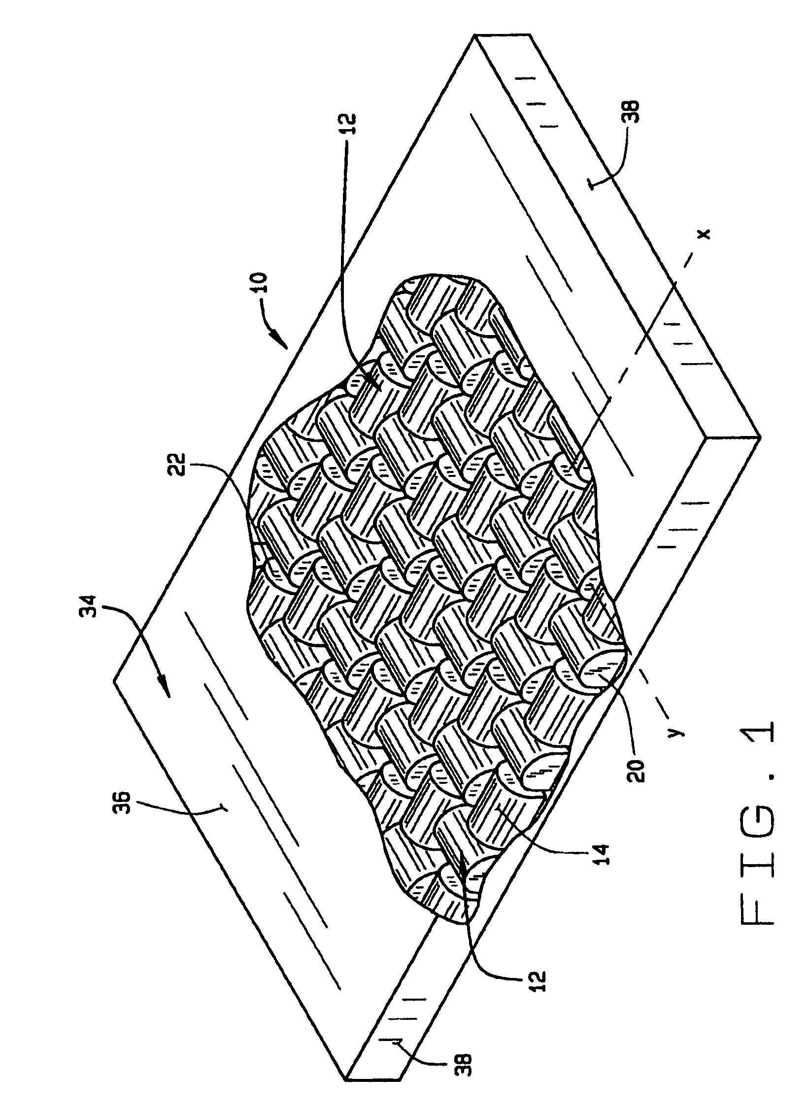
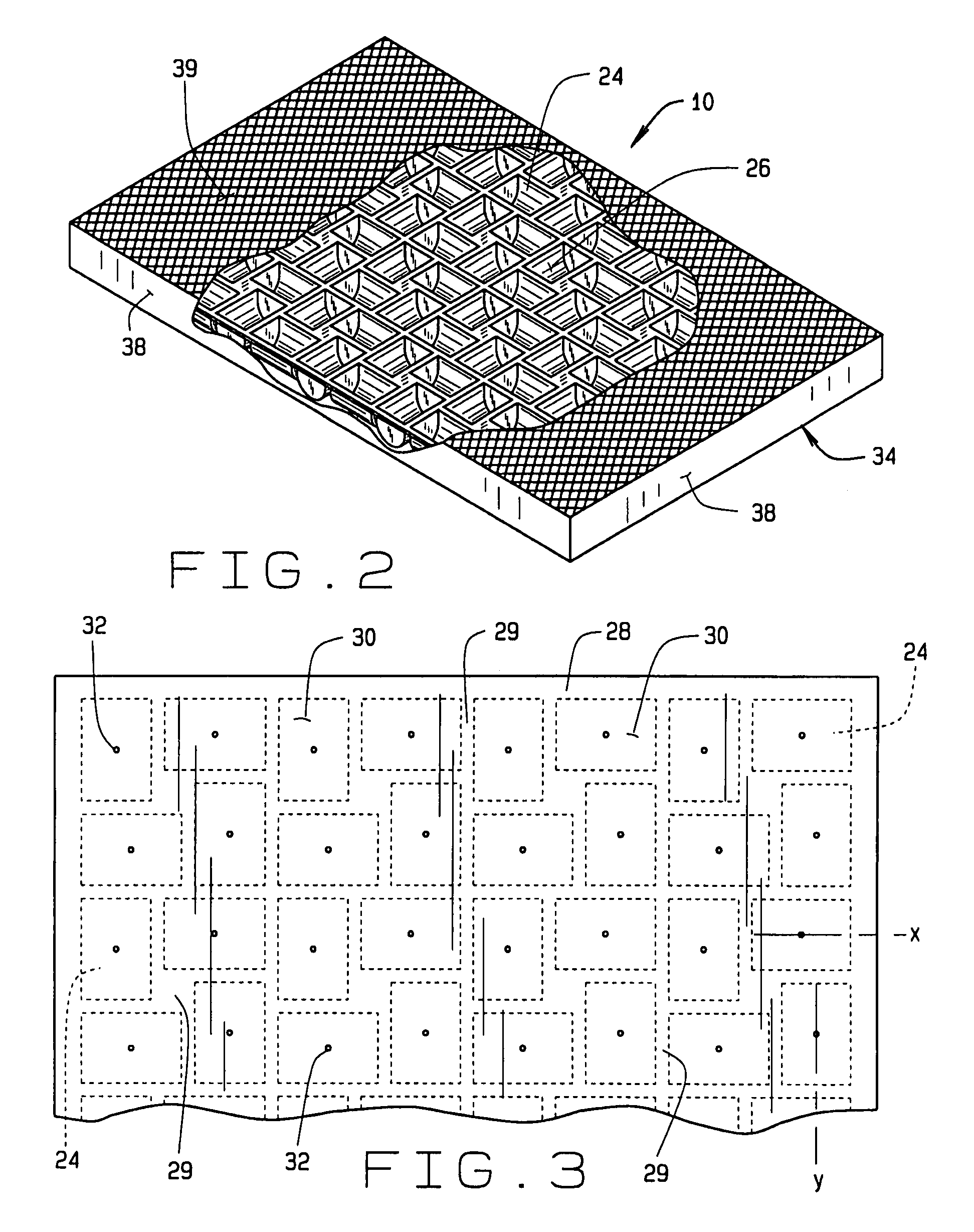
[0020]In general, the present invention provides for a cushion having an array of hollow suspension elements that create a displaceable constant restoring force, shape-matching surface. The suspension elements include a load-bearing surface, end walls, and an optional bottom wall or membrane that closes off the hollow suspension element. Each bottom wall, when present, has an optional vent of a predetermined size formed therein to allow venting of air from the hollow suspension element when force is exerted on the support surface. The base of each suspension element generally has rectangular configuration permitting a high density of suspension elements per area or cushion for more contact area to the supported person. The array of suspension elements is arranged in a pattern across the expanse of the cushion wherein the longitudinal axis of each suspension element is positioned at a right angle relationship to the longitudinal axis of the adjacent suspension elements. This results ...


PUM


Abstract

A cushion comprising an array of individual suspension elements arranged in a pattern wherein one embodiment the longitudinal axis of each suspension element in the array is positioned at a right angle or parallel to the longitudinal axes of the adjacent suspension elements. Each suspension element has a displaceable load-bearing surface, a first end wall, a second end wall, and an optional bottom wall, with load-bearing surface and recited walls defining an inner chamber. The material thickness of the load-bearing surface generally is greater than the material thickness of the end walls whereby the end walls deflect outwardly toward the load-bearing surfaces of adjacent support elements under load. The load-bearing surface can have a substantially arch-shaped, elliptical or rectangular cross-section and may be constructed from different materials to make a composite suspension element. The bottom wall of the suspension element may have a small vent opening of a predetermined size to allow a controlled release of air from the inner chamber under load to enhance the viscous feel of the cushion. The cushion also includes a cover enclosing the array of suspension elements.

Description

CROSS REFERENCE TO RELATED APPLICATIONS[0001]Not ApplicableBACKGROUND OF THE INVENTION[0002]The invention relates generally to support surfaces that facilitate blood flow and prevent tissue breakdown and more particularly to a molded foam cushion having suspension elements that are shaped and positioned to form a shape matching support surface that has relatively uniform restoring forces when deformed under loads from of a user.[0003]Individuals confined to bed or to a wheelchair run the risk of tissue breakdown and the development of ischemic induced sores, which are extremely dangerous and difficult to treat and cure. For example, when seated much of the individual's weight concentrates in the region of the ischia, that is, at the bony prominence of the buttocks, and unless frequent movement occurs, the flow of blood to the skin tissue in these regions decreases to the point that the tissue breaks down. When lying down, the hip region may protrude deeper into the mattress than the...

Claims


Application Information

Patent Timeline
Patent Type & Authority Patents(United States)
IPC IPC(8): A47C27/16
CPCA47C27/144A47C27/15A47C27/148A47C27/146
Inventor GRAEBE, ROBERT H
Owner ROHO
Why Eureka
Try Eureka