Map matching method, map matching device, database for shape matching, and shape matching device

a mapping method and technology for mapping devices, applied in traffic control systems, navigation instruments, instruments, etc., can solve the problems of a large amount of work, and the method of using the unified number requires maintenance and maintenance. , to achieve the effect of spanning a range of road networks

Active Publication Date: 2005-10-13
PANASONIC INTELLECTUAL PROPERTY CORP OF AMERICA
View PDF4 Cites 36 Cited by
  • Summary
  • Abstract
  • Description
  • Claims
  • Application Information

AI Technical Summary

Benefits of technology

[0030] To this end, in accordance with a map matching method of the present invention, with respect to road networks having an unequal condition in frequencies corresponding to a objective road of a map matching operation, priority orders are set in response to the frequencies; a road network which is matched with

Problems solved by technology

Since newly constructing operations of roads and route changes are not stopped in future, the method for using the unified numbers necessarily requires work loads of maintenance.
It should be noted that digital map databases may contain errors due to a fatal aspect of reduced scale maps.
As to the traffic information supplied by the above-explained traffic information providing system, for example, in such a case that latitude/longitude data as to a traffic jam position and a traffic accident position is solely provided in order to inform the traffic jam position and the traffic accident position, there is a risk that if both a traffic information providing source and a traffic information provided destination employ different sorts of digital map databases, then the on-vehicle navigation machine identifies a dif

Method used


Image

  • Map matching method, map matching device, database for shape matching, and shape matching device
  • Map matching method, map matching device, database for shape matching, and shape matching device
  • Map matching method, map matching device, database for shape matching, and shape matching device

Examples


second embodiment

MODE

[0237] In a second embodiment mode of the present invention, a description is made of an improvement in the process operation defined in the step 1 of FIG. 5, namely, an improvement in such a process operation that the map matching operation is carried out in the high-grade layer as high as being permitted.

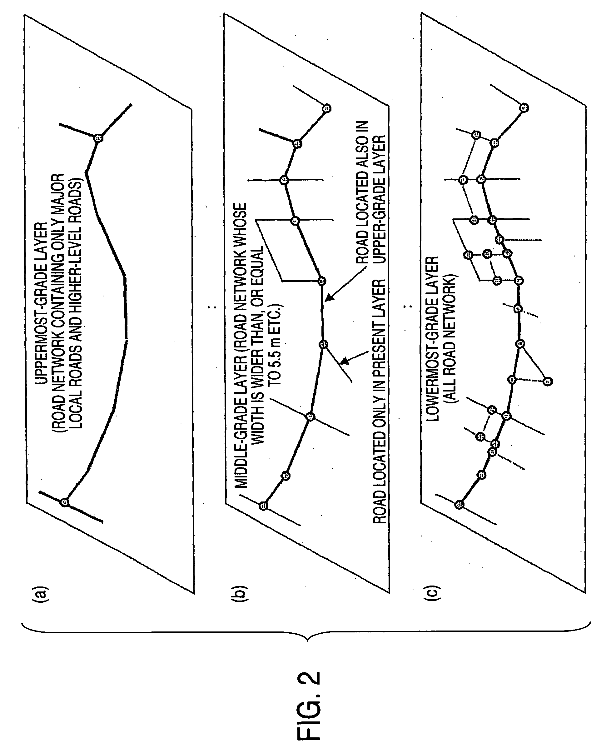
[0238] Since the road network data having the hierarchical layer structure has been originally classified to be formed on account of the map data held by the reception-sided device, the transmission-sided device normally cannot grape such items that which road section is contained in the upper-grade layer of this hierarchical layer structure, and which road section is contained in the lower-grade layer thereof. As a consequence, there are some possibilities that a road section of the upper-grade layer is mixed with a road section of the lower-grade layer within a single shape vector transmitted from the transmission-sided device.

[0239] In such a case, for example, even when ...

third embodiment

MODE

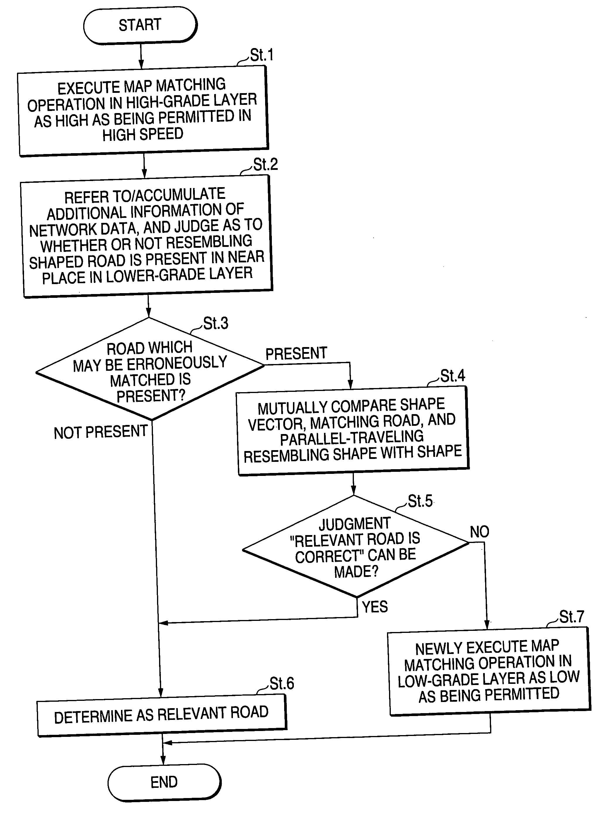
[0252] In a third embodiment mode of the present invention, a description is made of a method for performing a map matching operation in an upper-grade layer in a higher efficiency in the process operation defined in the step 1 of FIG. 5.

[0253] In such a case that a map matching operation is carried out by using road network data of an upper-grade layer, since an averaged link length is long, nodes may be set to WPs, which have been selected at intervals from a structural node column of shape vector.

[0254] Thus, in a first method, in such a case that the road network data of the upper grade layer is employed, a map matching operation is carried out by using such nodes as WPs. The nodes have been selected, for instance, every “N” pieces from the structural node column of the shape vector. As explained above, since the nodes are thinned (skipped) from the shape vector so as to be employed as WPs, a total number of WPs is decreased, and processing time of the map matching operati...

fourth embodiment

MODE

[0266] In a fourth embodiment mode of the present invention, a description is made of a method for performing a map matching operation in an upper-grade layer in a higher efficiency in the process operation defined in the step 1 of FIG. 5 by combining the first embodiment mode and the second embodiment mode with the third embodiment mode.

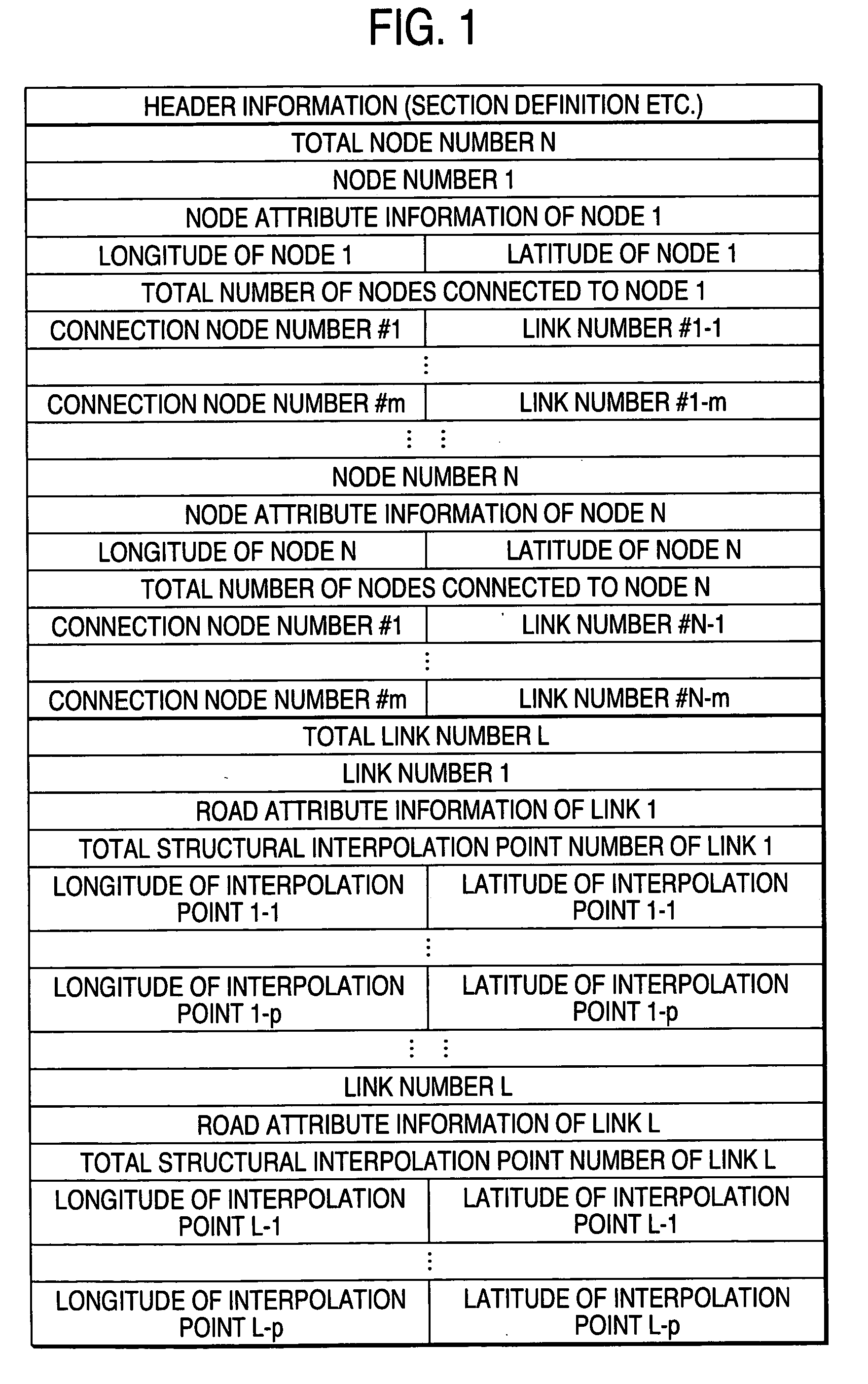
[0267]FIG. 21 indicates road network data (portion of hierarchical layer structure) in this embodiment mode. In this road network data, as link information, the data as to “uppermost layer number of present road” and “return distance when map matching operation is transferred to lower-graded layer) explained in the second embodiment mode are contained, and also, the data as to “recommended skip distance” explained in the third embodiment mode is contained.

[0268] Also, a flow chart of FIG. 22 indicates a map matching method in this embodiment mode. FIG. 23 schematically shows this map matching method. In this case, the flow chart indicates that...


PUM


Abstract

An object of the present invention is to provide a map matching method capable of performing a process operation in a high speed. In the map matching method of the present invention, while employing road network data in which road networks are formed in a plurality of hierarchical layers “a”, “b”, “c”, and a road network of an upper-grade hierarchical layer is established by such a road network which is extracted from a road network having a lower-grade hierarchical layer lower than the road network having the upper-grade hierarchical layer, a road network of the uppermost-grade hierarchical layer “a” is matched with a shape vector indicative of a shape of a objective road in a beginning stage; and when such a candidate road which is matched with the shape vector cannot be obtained in the road network of the uppermost-grade hierarchical layer “a”, since such a road network having another hierarchical layer “b”, or “c” is matched with the shape vector, the objective road is identified. In the most cases, as to a objective road of traffic information and the like, the objective road can be identified by executing a map matching operation with employment of the road network having the uppermost-grade hierarchical layer “a”, and the map matching operation can be carried out in a high speed.

Description

TECHNICAL FIELD [0001] The present invention is related to a map matching method, an device for executing the map matching method, and a computer program. More specifically, the present invention is directed to a map matching method, a map matching device, and a computer program, capable of a performing map matching operation in a high speed. Also, the present invention relates to an information transferring method for transferring positional information as to a traffic jam, a traffic accident, and the like in a traffic information providing system, or the like, and relates to an device for performing an information exchanging operation as to a position by using this information transferring method. In particular, the present invention is directed to a shape matching-purpose database and a shape matching device, capable of firmly and rapidly transferring a position on a digital map. BACKGROUND ART [0002] Conventionally, for instance, as described in the below-mentioned patent public...

Claims


Application Information

Patent Timeline
IPC IPC(8): G06Q10/00G09B29/10
CPCG06Q10/047G09B29/106G09B29/10G01C21/30G09B29/00
Inventor ADACHI, SHINYASATO, MAKOTO
Owner PANASONIC INTELLECTUAL PROPERTY CORP OF AMERICA
Why Eureka
Try Eureka