
Composite switch device

A composite switch and switch technology, applied in electrical switches, emergency protection devices, electrical components, etc., can solve the problems of insulation, difficult to adjust the switching time, and the reduction of the contact state of movable contacts and fixed contacts.

Inactive Publication Date: 2005-05-18
U SHIN LTD
View PDF1 Cites 2 Cited by
  • Summary
  • Abstract
  • Description
  • Claims
  • Application Information

AI Technical Summary

Problems solved by technology

[0009] In particular, since multiple switches are accommodated in a compact switch body in a composite switch unit, the distance from the center of rotation of the operating lever to the engaging member that slides the movable plate is shortened. If you want to switch the switches reliably, then Since the distance between the movable contact and the fixed contact must be shortened, there is a problem of insulation. On the contrary, if the distance between the movable contact and the fixed contact has a margin, there is a difference between the movable contact and the fixed contact. The risk of reduced contact state between
[0010] In addition, these switches must switch multiple movable contacts and fixed contacts at the same time. However, if the operating angle of the operating lever is small, the movement amount of the movable plate is also small, so it is difficult to adjust the switching timing of each contact part. On the contrary, if the operating angle of the operating lever is increased, the operability is poor, and the moving amount of the movable plate also increases, so problems such as an increase in the size of the switch main body arise.

Method used


Image

  • Composite switch device
  • Composite switch device
  • Composite switch device

Examples


Embodiment Construction

[0046] Embodiments of the present invention will be described below according to the accompanying drawings.

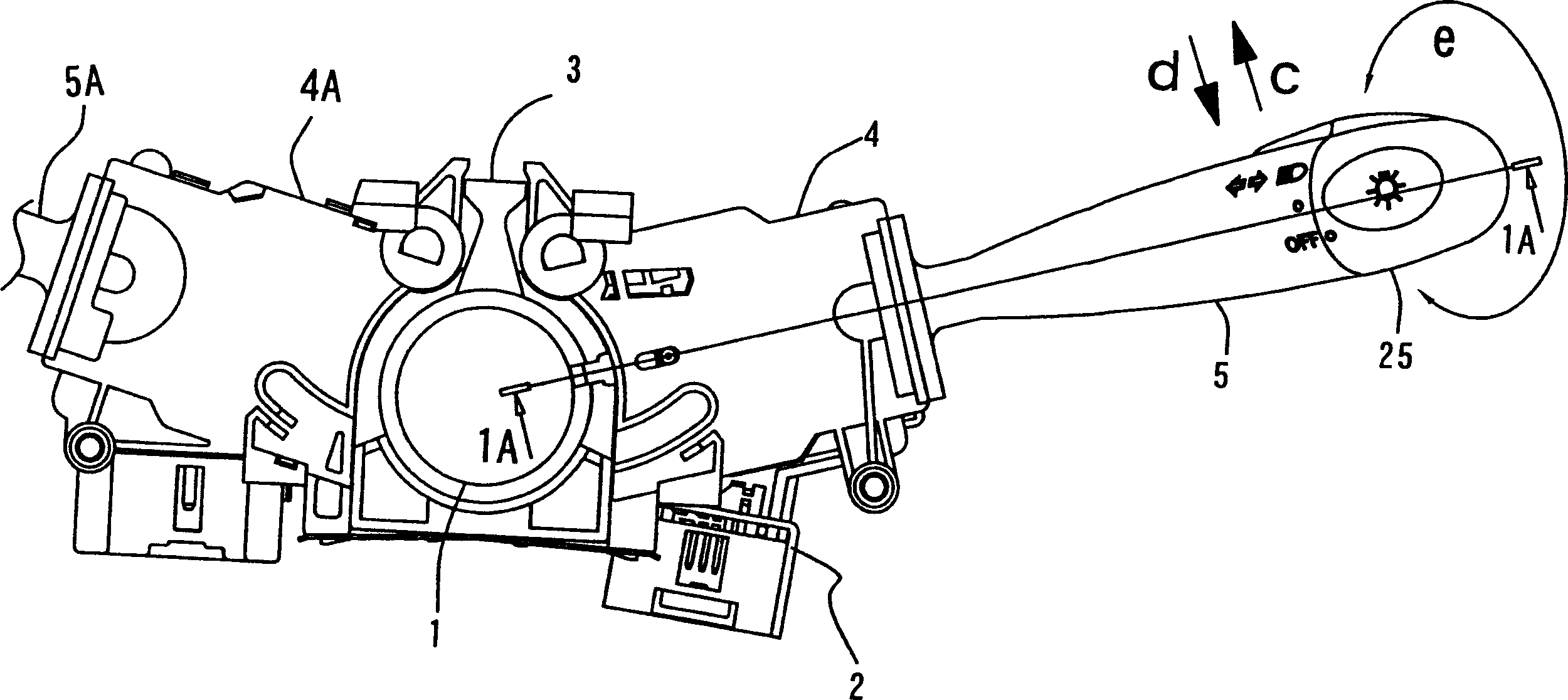
[0047] figure 1 Shown is the steering shaft 1 and its surroundings on which a steering wheel (not shown) for steering the car is mounted.

[0048] On a peripheral portion of the manipulation shaft 1, a mounting portion 3 is provided to which the combined switch device 2 can be mounted from the side.

[0049] The mounting portion 3 is provided, for example, on a steering lock (not shown in the figure), and the composite switch device 2 is integrally mounted on the steering lock (steering lock).

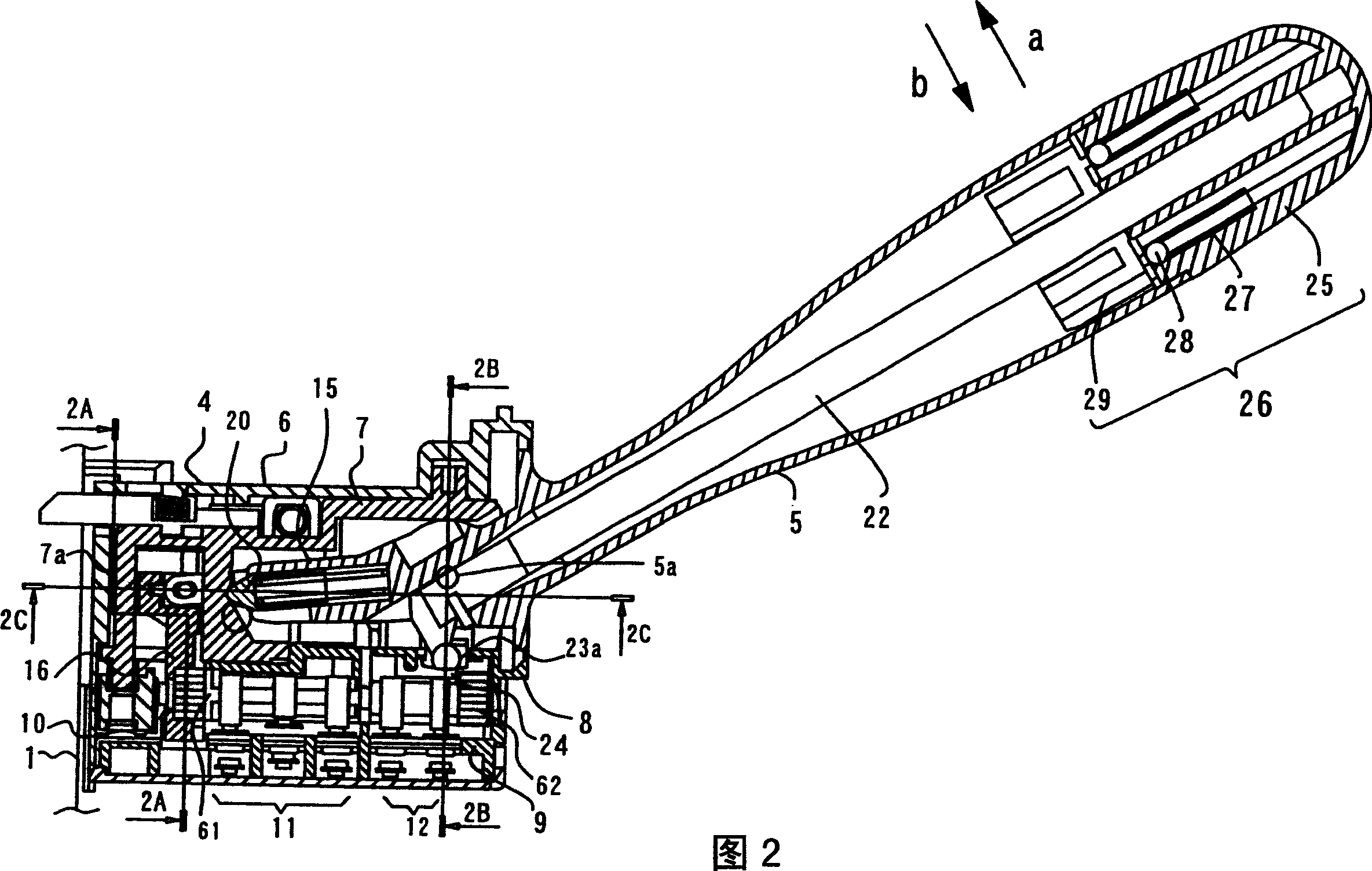
[0050] The composite switch device 2 is composed of a switch main body 4 and an operating rod 5 , and the operating rod 5 is rotatable in the up-down or front-back direction of the switch main body 4 .

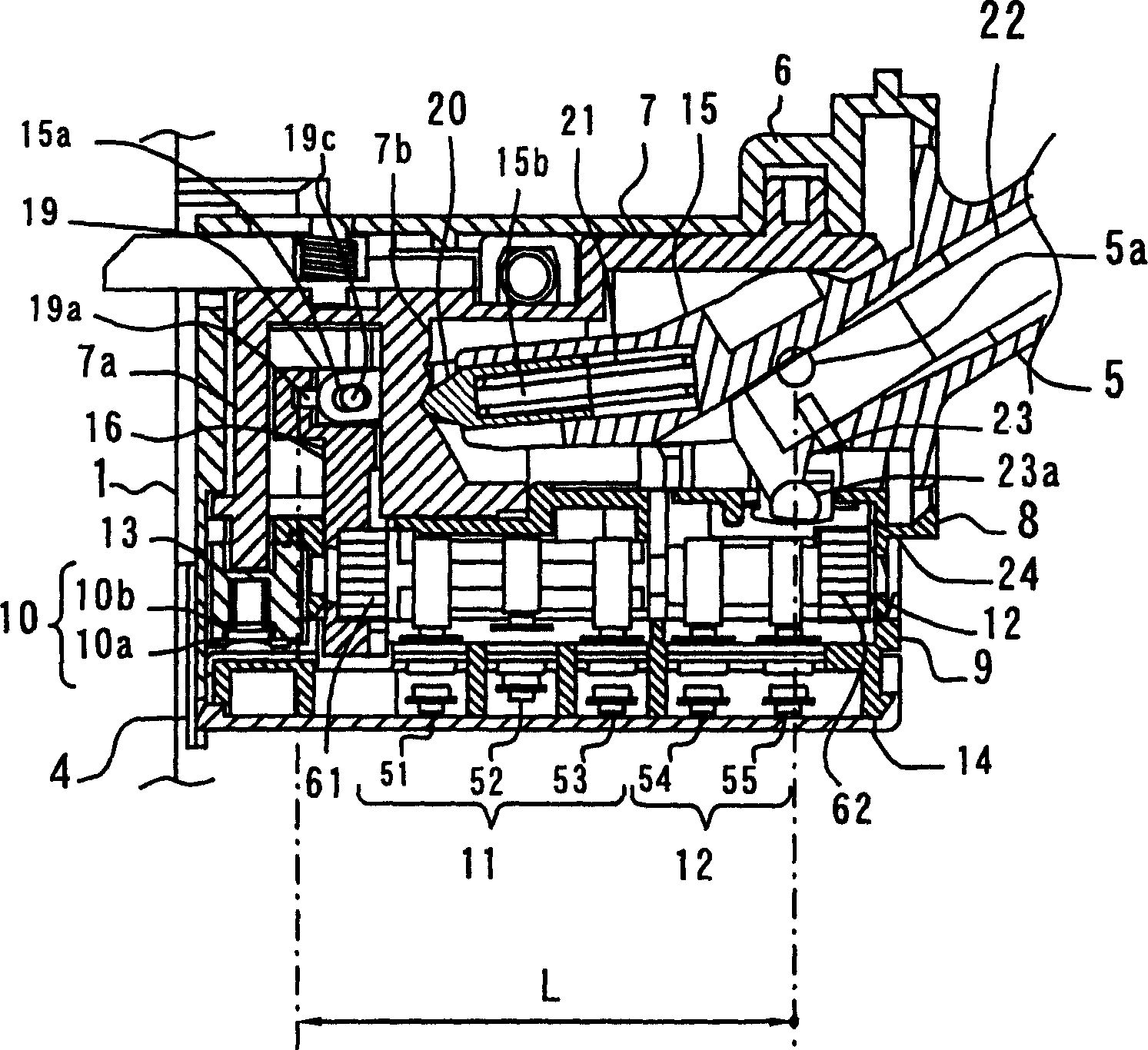
[0051] exist figure 1 Shown inside the switch body 4, like image 3 As shown, a switch 10, a dimmer switch 11, and a dimming cam 12 are provided, and inside the switch main...


PUM


Abstract

The present invention provides a composite switch device capable of switching a plurality of movable contacts and fixed contacts reliably. The composite switch device includes a switch main body and an operating rod. A plurality of switches with movable contacts and fixed contacts are assembled in the switch main body. The operating rod is arranged on the switch main body. To operate, the composite switch device includes a rod with a rack, which moves linearly with the action of one end of the operating rod; Moving linearly and rotating, the contacts of the above-mentioned switches are selectively operated by the above-mentioned cam, and even if the distance between the movable contact and the fixed contact has a margin, it can still be operated according to the less operation of the operating lever. Quantitatively realize the switching action.

Description

technical field [0001] The present invention relates to a composite switch device for switching a plurality of switches such as a dimmer switch and a light switch of an automobile by operating a lever. Background technique [0002] An operation unit for turning on a blinker or a headlight of an automobile is generally provided in a composite switch unit provided around a steering shaft on which a steering wheel of the automobile is mounted. [0003] The composite switch assembly is composed of an operating rod and an internal structure of a switch main body provided on the base end (support portion) side of the operating rod. [0004] Such a composite switch assembly is constituted in the following manner: a light switch for turning on the headlights and position lights, a dimmer switch for turning on the high beam or low beam to switch the lighting direction of the headlights, Various switches, such as a turn signal switch for turning on the blinker, are collectively insta...

Claims


Application Information

Patent Timeline
Patent Type & Authority Applications(China)
IPC IPC(8): H01H25/04H01H25/00H01H89/00
Inventor 森园和则
Owner U SHIN LTD
Learn More