Resonator with retention ribs

A resonator and resonant cavity technology, applied in the direction of intake mufflers, machines/engines, charging systems, etc., can solve problems such as performance degradation

Inactive Publication Date: 2005-07-13
FLEETGUARD INC
View PDF0 Cites 22 Cited by
  • Summary
  • Abstract
  • Description
  • Claims
  • Application Information

AI Technical Summary

Problems solved by technology

Other configurations can be made without gas seals if cost is reduced, but performance will be degraded as a result

Method used


Image

  • Resonator with retention ribs
  • Resonator with retention ribs
  • Resonator with retention ribs

Examples


Embodiment Construction

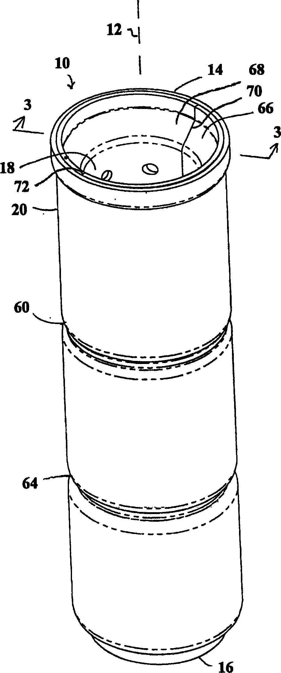
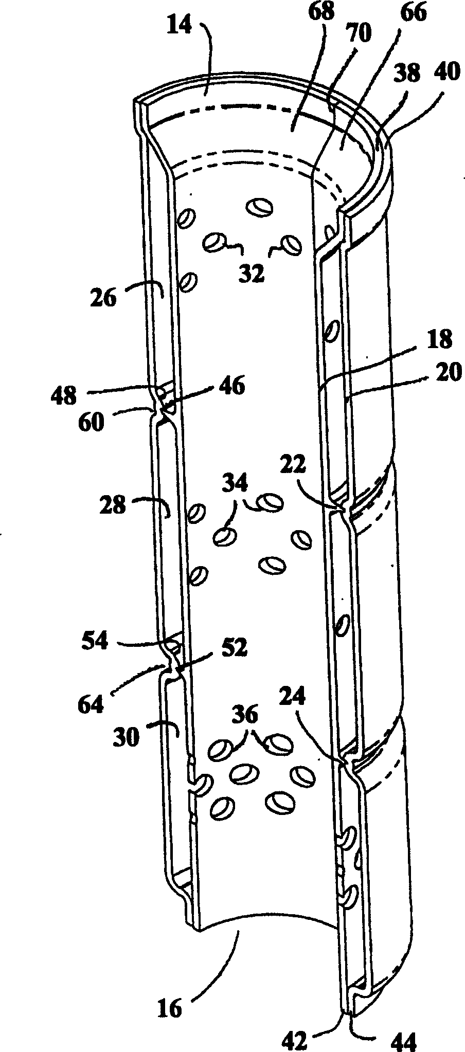
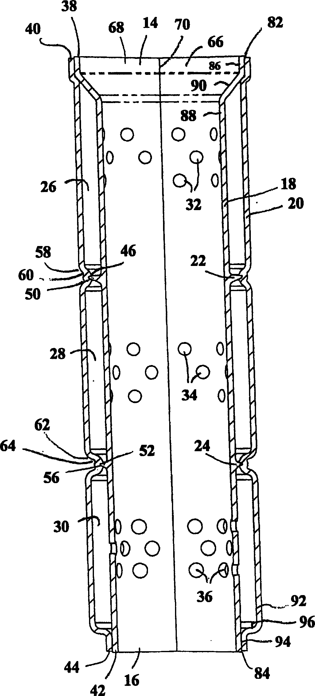
[0008] figure 1 Resonator 10 is shown extending along axis 12 between two axially opposite ends 14 and 16 which provide an inlet and an outlet respectively, such as at inlet 14 to receive drawn-in combustion air, Combustion air is delivered from outlet 16 to an internal combustion engine (not shown). Such as Figure 2-4 As shown, the resonator 10 has an inner porous tube 18, a housing 20 and at least one and preferably two or more annular ribs such as 22, 24 which are axially spaced between the inlet 14 and the outlet 16 and which are separated in the inner porous tube 18 and the shell 20 extend along the radial direction. In a preferred form, the inner perforated tube 18 is an injection molded piece of plastic and the outer shell 20 is a molded or rotationally molded piece of plastic, and the ribs are integral radially outwardly from the inner perforated tube 18 extend out. These ribs define a first resonant cavity 26 axially upstream of the rib 22, between the inner perf...


PUM


Abstract

A resonator includes an inner porous tube, a housing and a plurality of annular ribs extending radially between the inner porous tube and the housing and defining a resonant cavity. The progressive step of the ribs and grooves enables an axially inserted assembly with a minimum of effort. This eliminates the need for welding or secondary bonding operations.

Description

technical field [0001] The present invention relates to resonators, including air intake resonator mufflers for internal combustion engines. Background technique [0002] Inlet resonators are known in the art and can be fabricated from a variety of materials including metal and / or plastic. Formed bottle resonators are known which are fitted under the hoods of automobiles, trucks, agricultural vehicles, construction vehicles, boats and recreational vehicles. Various constructions use hollow structures made of plastic that are joined together using vibration or sonic welding and other forms of friction welding. Other types of construction also have elastomeric seals at an added cost. Other configurations can be made without the gas seal if cost is reduced, but performance will be degraded as a result. Contents of the invention [0003] The present invention provides a simple and economical resonator without sacrificing performance. Description of drawings [0004] fig...

Claims


Application Information

Patent Timeline
Patent Type & Authority Applications(China)
IPC IPC(8): F01N1/02F01N1/08F02B27/02F02M35/104F02M35/12
CPCF01N1/02F02M35/1216F02M35/1266
Inventor 杰西·艾伦·奈特迈克尔·J·康纳
Owner FLEETGUARD INC
Why Eureka
Try Eureka