Driving circuit of liquid crystal display

A technology of liquid crystal display device and driving circuit, applied in static indicators, static memory, instruments, etc., can solve problems such as screen flickering and reducing picture quality.

Active Publication Date: 2005-07-13
HYDIS TECH CO LTD
View PDF0 Cites 6 Cited by
  • Summary
  • Abstract
  • Description
  • Claims
  • Application Information

AI Technical Summary

Problems solved by technology

However, in the above situation, when the panel drive is line inversion, the screen flickers (flicker) and there is a problem that the image quality is significantly reduced.

Method used


Image

  • Driving circuit of liquid crystal display
  • Driving circuit of liquid crystal display
  • Driving circuit of liquid crystal display

Examples


Embodiment Construction

[0034] Hereinafter, the liquid crystal display device of the present invention will be described with reference to the drawings.

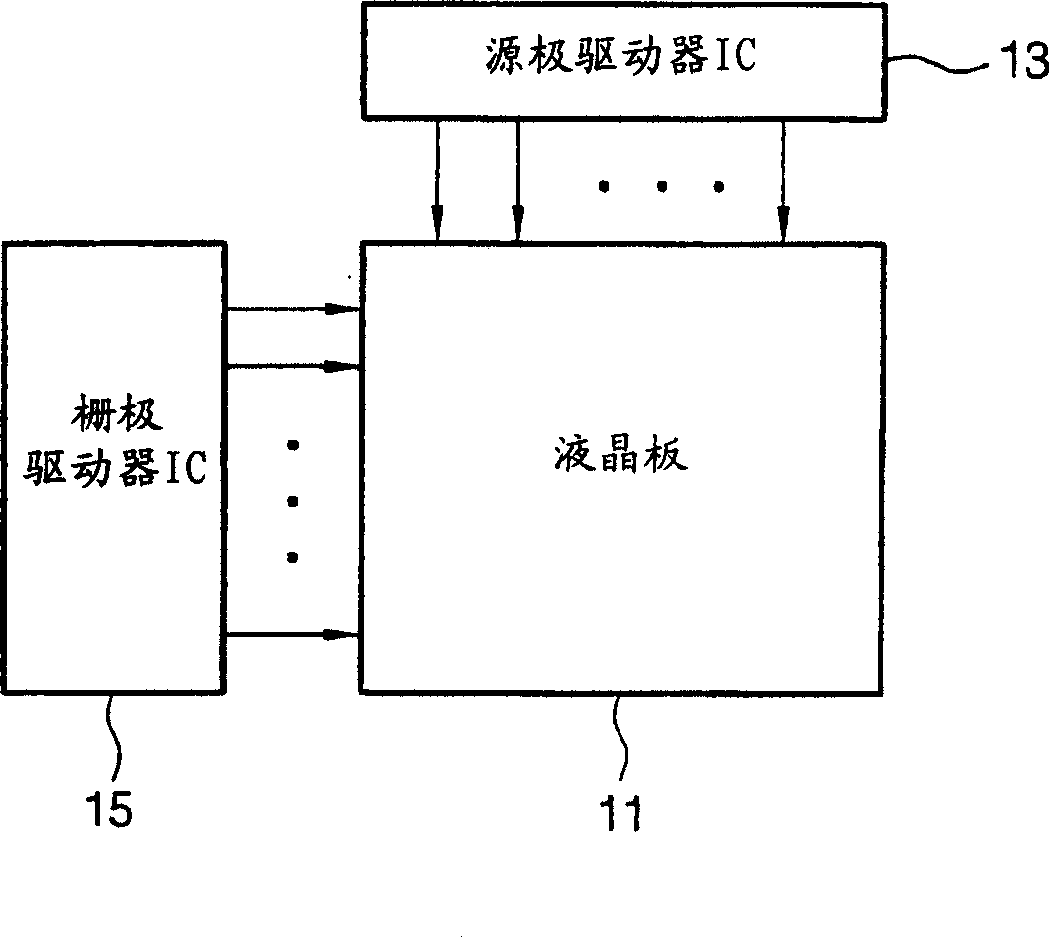
[0035] Figure 5 It is a figure which shows the drive circuit of the liquid crystal display device of this invention.

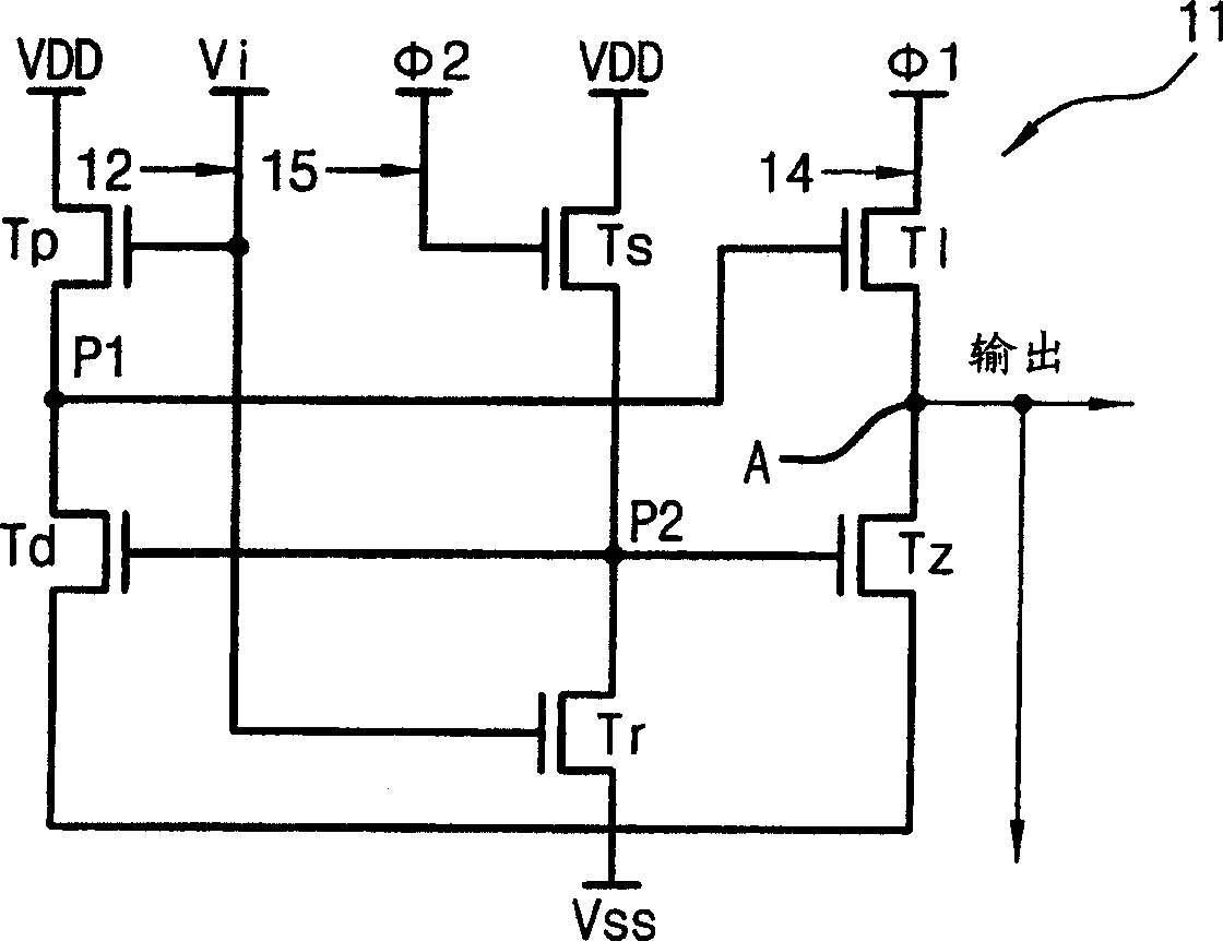
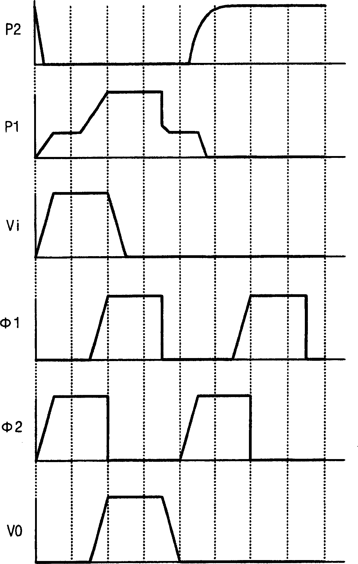
[0036] The driving circuit of the liquid crystal display device of the present invention is as Figure 5 As shown, it consists of 8 thin film transistors T1, T2, T3, T4, T5, T6, T7, T8 and 2 capacitors C1, C2.

[0037] That is, if Figure 5 As shown, the gate terminal and the drain terminal of the first transistor T1 are commonly connected to the n-1th gate line, and the second transistor T2 is connected between the source terminal of the first transistor T1 and the Vss terminal, and the clock The third transistor T3 driven by the signal Clk is connected in series with the fourth transistor T4 connected to the Vss terminal. At this time, the connection point between the source terminal of the third transistor T3 and the drain ...


PUM


Abstract

The present invention provides a driving circuit of a liquid crystal display device, which improves the Vgoff characteristics of the driving circuit composed of 4 thin film transistors and 2 capacitors, and makes the characteristic change of the thin film transistor caused by the DC stress of the driving circuit composed of 6 thin film transistors minimum, so that the operating characteristics are stable. The drive circuit of the liquid crystal display device includes: the first and second transistors are connected in series between the output stage of the n-1 circuit and the Vss stage; the third transistor is driven by a clock signal; the fourth transistor is connected to the drain To the source of the third transistor; the fifth and sixth transistors are connected in series between the VDD terminal and the Vss terminal; the seventh transistor is driven by the output signal of the n+1 circuit; the eighth transistor is driven by the n+ The output signal of the circuit 1 is driven; the first capacitor is formed before the gate of the third transistor; and the second capacitor is formed between the gate and drain of the sixth transistor.

Description

technical field [0001] The present invention relates to a driving circuit of a liquid crystal display device, in particular to a liquid crystal display device suitable for improving the stability of the off-level of an output signal and the change of element characteristics based on DC voltage stress (voltage stress), thereby greatly improving the operating characteristics of the circuit Drive circuit. Background technique [0002] Generally, a CRT (Cathode Ray Tube; Cathode Ray Tube), which is one of display devices, is mainly used for monitors of various measuring equipment, information terminals, etc., represented by televisions. However, due to the weight and size of the CRT itself, It cannot meet the requirements of miniaturization and light weight of electronic products. [0003] Therefore, in order to replace CRTs, liquid crystal display devices having advantages of thinness and miniaturization are being actively developed, and are currently being developed to the ex...

Claims


Application Information

Patent Timeline
Patent Type & Authority Applications(China)
IPC IPC(8): G02F1/133G09G3/20G09G3/36
CPCG09G3/3677G09G2300/0408G11C19/184G09G3/36
Inventor 安星俊金天弘柳世钟
Owner HYDIS TECH CO LTD
Why Eureka
Try Eureka