Fiber cutting machine used for producing staple fibers

A technology of fiber cutting machine and artificial filament, which is applied in fiber cutting, fiber processing, textile and paper making, etc. It can solve the problems of blade wear, low hardness, and inability to cut neatly, and achieve the effect of reducing bending load

Active Publication Date: 2017-06-13
OERLIKON TEXTILE GMBH & CO KG
View PDF9 Cites 0 Cited by
  • Summary
  • Abstract
  • Description
  • Claims
  • Application Information

AI Technical Summary

Problems solved by technology

However, this material is not suitable for use as a cutting tool because it has a low hardness and the cutting edge wears out quickly
A blade so worn makes it impossible to cut cleanly

Method used


Image

  • Fiber cutting machine used for producing staple fibers
  • Fiber cutting machine used for producing staple fibers
  • Fiber cutting machine used for producing staple fibers

Examples


Embodiment Construction

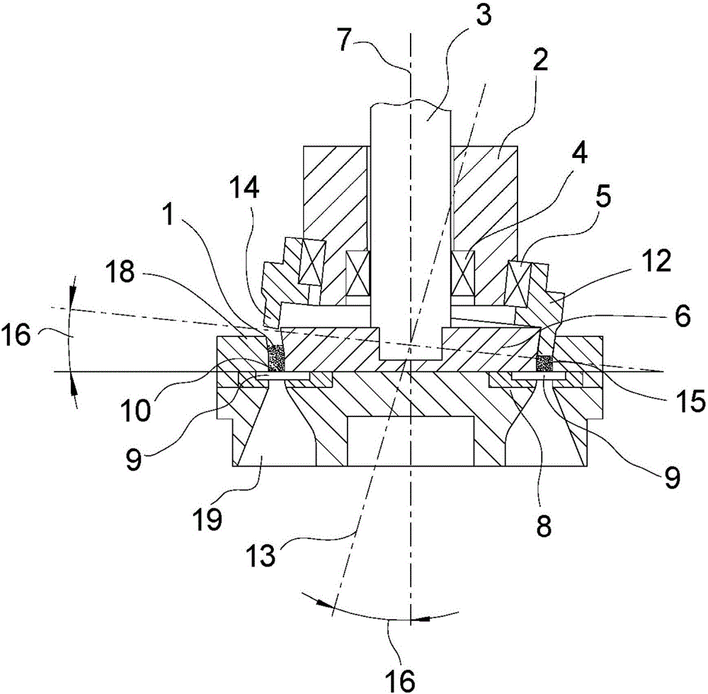
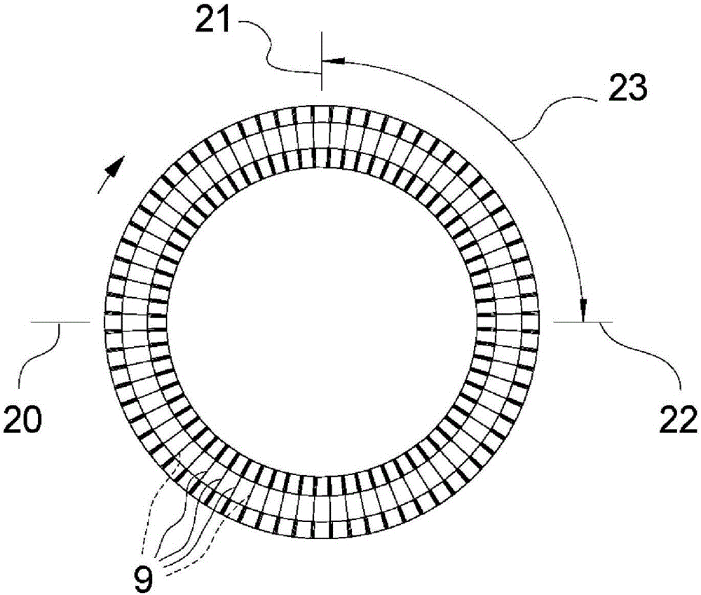
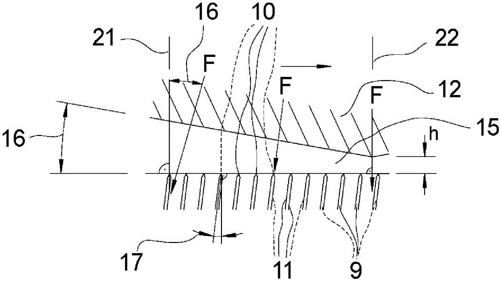
[0020] All three figures have the same reference numerals. exist figure 1 A cross-sectional view of an embodiment of a fiber cutter according to the present invention is schematically shown in . A plurality of tools 9 are arranged in a ring and are held horizontally in the associated tool receptacle 8 . A tool receptacle 8 is arranged in the tool holder 6 . The tool holder 6 is rotatable via the drive shaft 3 . The axis of rotation is formed by the tool carrier axis 7 , which runs centrally through the tool carrier 6 and the drive shaft 3 . The drive shaft 3 is held in a stationary bearing housing 2 by means of bearings 4 . Furthermore, the bearing housing 2 accommodates on its outer circumference a pressure ring bearing 5 , by means of which a pressure ring 12 is held rotatably on the bearing housing 2 . The pressure ring 12 and the associated pressure ring carrier 5 are arranged such that an opening angle 16 is formed between the pressure ring axis 13 , about which the ...


PUM


Abstract

The invention relates to a fiber cutting machine used for producing staple fibers. In the production of staple fibers, a tow of a plurality of polymeric filaments is cut into short staple fibers in the fiber cutting machine. In the known fiber cutting machines, knives of which have horizontally arranged knife edges, the knife flanks of the knives are arranged parallel to a knife rest axis. When the fiber cutting machine is used, the knife often fractures. The object of the present invention is to provide a fiber cutting machine with a horizontally arranged knife edge, which has a low risk of knife fracture without affecting the performance and the cutting power. This fiber cutting machine is achieved by oblique arrangement of the knife. The knife flank of the knife has a knife angle relative to the knife rest axis. By means of the fiber cutting machine according to the invention, particularly economic production of staple fibers can be realized.

Description

technical field [0001] The invention relates to a fiber cutter for producing staple / staple fibers according to the preamble of claim 1 . Background technique [0002] For the production of staple fibers, fiber cutting plants are known in which short staple fibers are produced from tows composed of man-made fibers. The device is designed either as a single-stage or as a two-stage. The single-stage process consists of melt spinning of the rayon, consolidating it into tow, drawing of the tow and further heat treatment. In addition, the rayon is crimped, if necessary, in a crimper. Finally, the tow is cut into staple fibers in a fiber cutter. In the second stage of the process, the man-made fibers merged into fiber bundles are stored in storage jugs during this time. In so-called fiber lines, fiber bundles are drawn from a plurality of storage jugs, from which fiber bundles are formed into tows. In the fiber production line, further processing of the tow takes place, the to...

Claims


Application Information

Patent Timeline
Patent Type & Authority Applications(China)
IPC IPC(8): D01G1/00
CPCD01G1/00D01G1/04
Inventor W-M·卡尔森-布拉克R·布莱斯莫尔
Owner OERLIKON TEXTILE GMBH & CO KG
Why Eureka
Try Eureka