Torque coupler

A technology of coupler and spring shock absorber, applied in the direction of coupling, elastic coupling, spring/shock absorber, etc., can solve problems such as reducing the service life of the connection, achieve compact design, reduce bending load, improve The effect of the service life

Active Publication Date: 2015-05-13
SCHAEFFLER TECH AG & CO KG
View PDF6 Cites 5 Cited by
  • Summary
  • Abstract
  • Description
  • Claims
  • Application Information

AI Technical Summary

Problems solved by technology

This construction has the disadvantage that during operation of the torque coupling not only the spacer pins or the riveted connection are subjected to shear stresses, but also bending forces also act additionally which can reduce the service life of the connection

Method used


Image

  • Torque coupler
  • Torque coupler
  • Torque coupler

Examples


Embodiment Construction

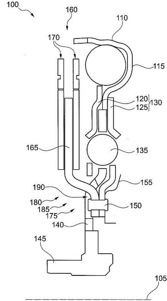
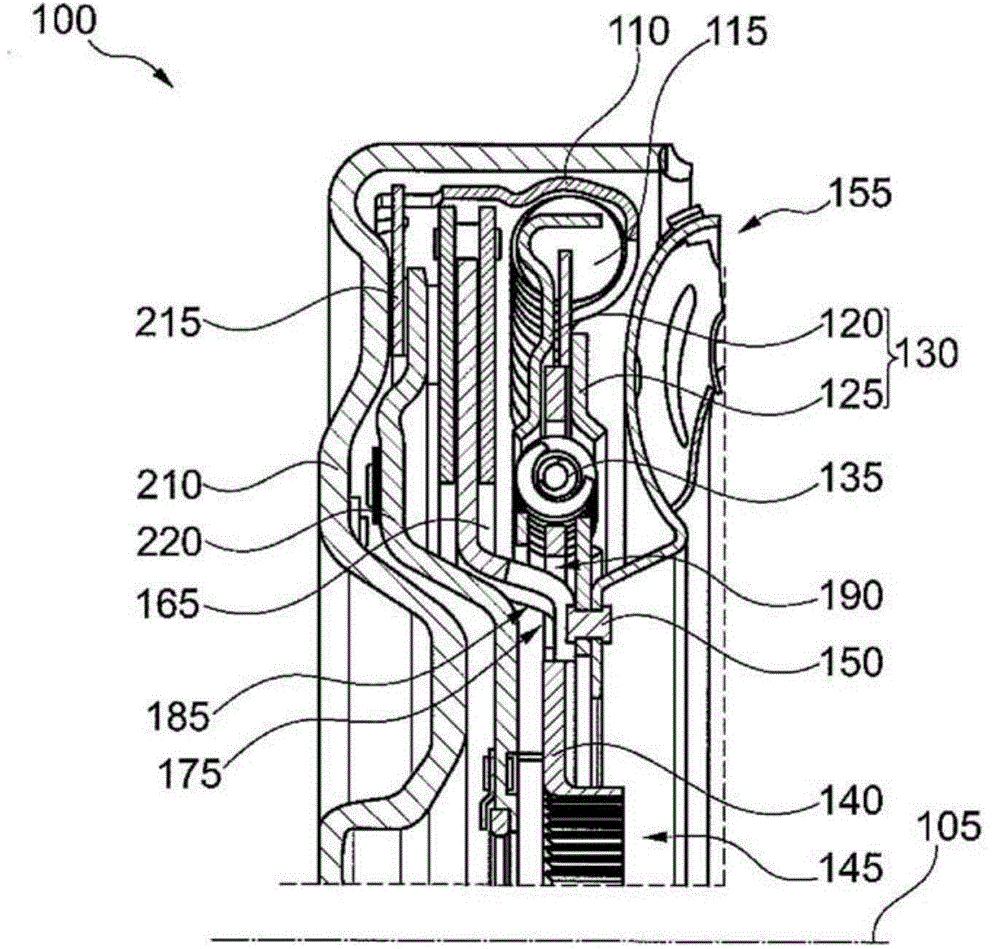
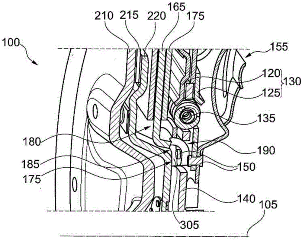
[0020] figure 1 A cross-sectional view of the torque coupler 100 is shown. The illustration only shows the upper half of the longitudinal section through the axis of rotation 105, the elements of the torque coupler 100 being arranged in a rotatable manner about the axis of rotation.

[0021] The torque coupler 100 shown includes a holding element 110 for connection with the input side of the torque introduced not shown, a first elastic element 115, a first disc element 120 (on the left here), and a first disc element (on the right here). 的) The second disc element 120, wherein the intermediate disc 130 includes disc elements 115 and 120; in addition, the torque coupler includes a second elastic element 135, an output flange 140, a hub 145, a connecting element 150, figure 1 The turbine 155 and the centrifugal force pendulum 160 are only briefly outlined in, and the centrifugal force pendulum includes a pendulum flange 165 and a pendulum mass 170.

[0022] Not all the components of t...


PUM


Abstract

A torque coupler comprises an input side and an output side, which are rotatably disposed about a rotational axis, further an intermediate disk for coupling to the input side, an output flange for coupling to the output side, a spring damper for coupling the intermediate disk to the output flange and a centrifugal-force pendulum having a pendulum flange and a pendulum mass. The pendulum flange extends between a first region, in which the pendulum flange is fastened to the intermediate disk, and a second region, in which the pendulum mass is mounted on the pendulum flange. The output flange has a cutout section through which a portion of the pendulum flange connecting the two regions runs.

Description

Technical field [0001] The invention relates to a torque coupler, especially used in the drive train of a motor vehicle. Background technique [0002] Torque couplers are used for torque transmission in the drive train of motor vehicles. The torque coupling provides, on the one hand, a torque-locked connection between the driven shaft of the drive motor and the drive shaft of the transmission, and on the other hand is provided for damping or eliminating torsional vibrations that are superimposed on the transmitted torque. To this end, the torque coupler includes a spring damper and a centrifugal force pendulum. The spring damper includes an elastic element whose end is connected to the input side or the output side of the torque coupler so as to compress or decompress the spring damper under the influence of the torque change. The centrifugal force pendulum includes a pendulum flange, and the pendulum mass is arranged on the pendulum flange in a manner that can move in the plan...

Claims


Application Information

Patent Timeline
Patent Type & Authority Applications(China)
IPC IPC(8): F16F15/14
CPCF16F15/145F16D3/66F16F15/13484
Inventor J·霍夫曼
Owner SCHAEFFLER TECH AG & CO KG
Why Eureka
Try Eureka