One aspect underlying the disclosure is to provide an actuator of the type mentioned in the beginning which is very fail-safe, structurally simple and nevertheless inexpensive.
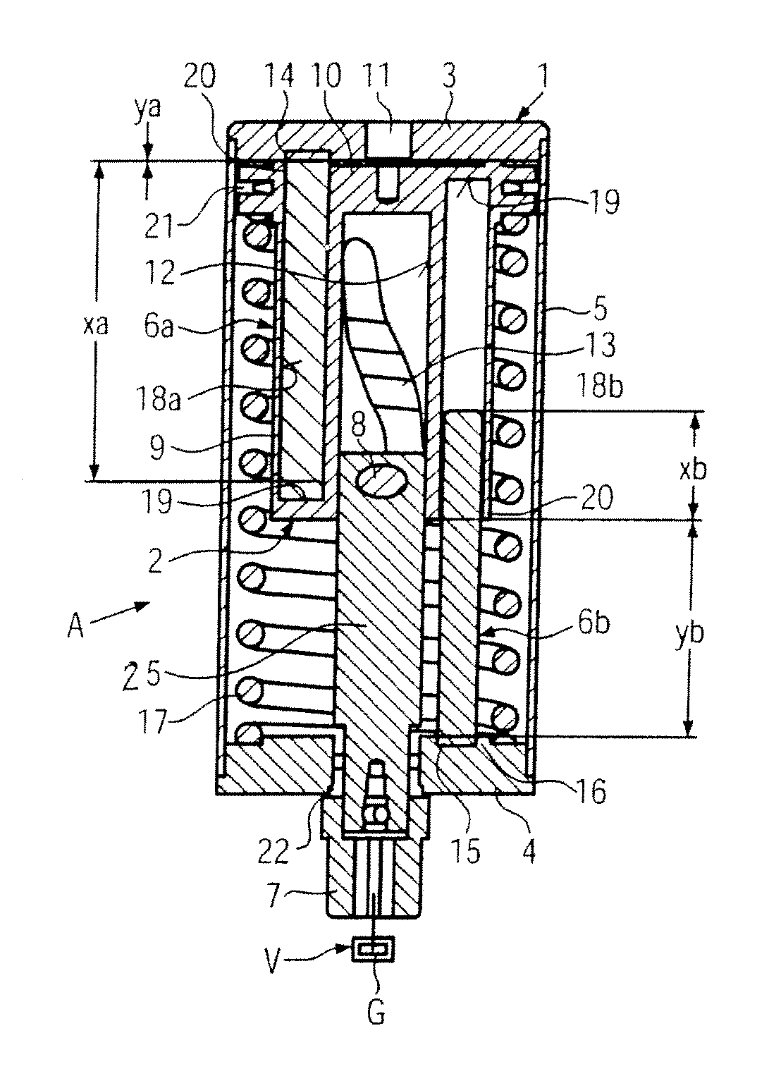
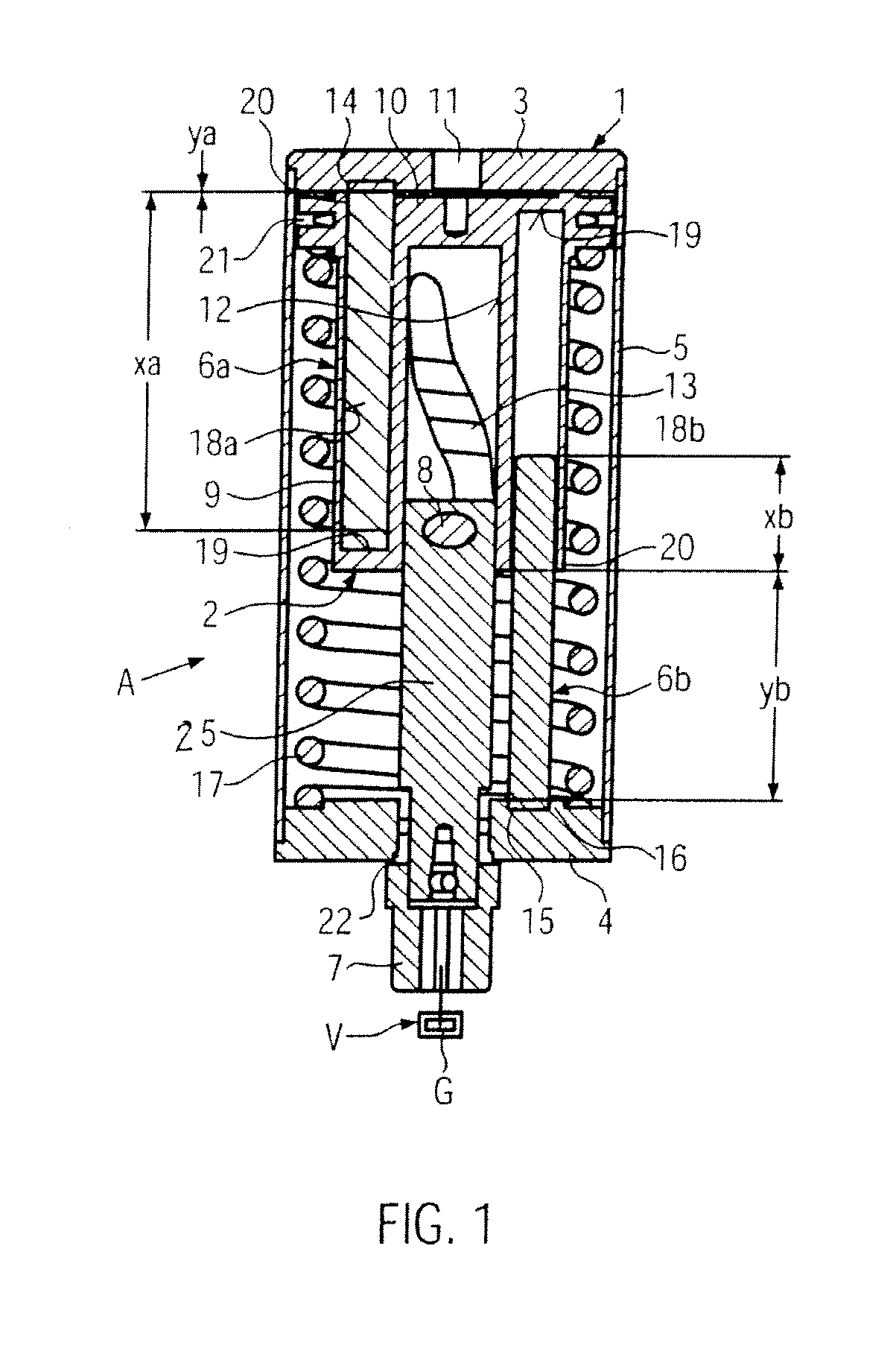
As the end of the one guide rod is anchored in one cover and the end of the other guide rod is anchored in the other cover of the housing, the free effective bending length of a guide rod is a minimum in each end position of the piston, so that the bending loads and bending stresses of this guide rod are also minimal. while its guide length simultaneously is a maximum, so that the specific
surface pressure between the guide and the guide rod remains low, even if the reaction moment to be transmitted then is a maximum. The guide rod whose free effective bending length is a minimum thus relieves the other guide rod of the load, whose free effective bending length then is a maximum. This altogether reduces the bending loads and bending stresses for the two guide rods, and this in the anchoring regions as well as in the mouths of the guides. This is accompanied by a reduction in wear of the guide rods in the guides. Though in the
stroke motion of the piston from the respective end position, the free effective bending length of the guide rod whose free effective bending length initially was a minimum increases, the free effective bending length of the other guide rod is at the same time reduced, so that the reaction torque is transmitted without problems over the
stroke distance of the piston while the bending stresses are reduced for both guide rods. The anchoring regions, e.g. welding regions, are less loaded, reducing the risk of damages and simultaneously sensibly increasing operational and process reliability, respectively. Due to the lower bending loads of the guide rods, the latter can be made of an inexpensive material, optionally of the same material as the covers. This facilitates anchorage, for example by welding. The actuator only consists of a small number of parts and can be inexpensively manufactured, as the manufacture of the anchorage region, for example, can be automated and the guide rods possibly do not require any readjustment. As in both
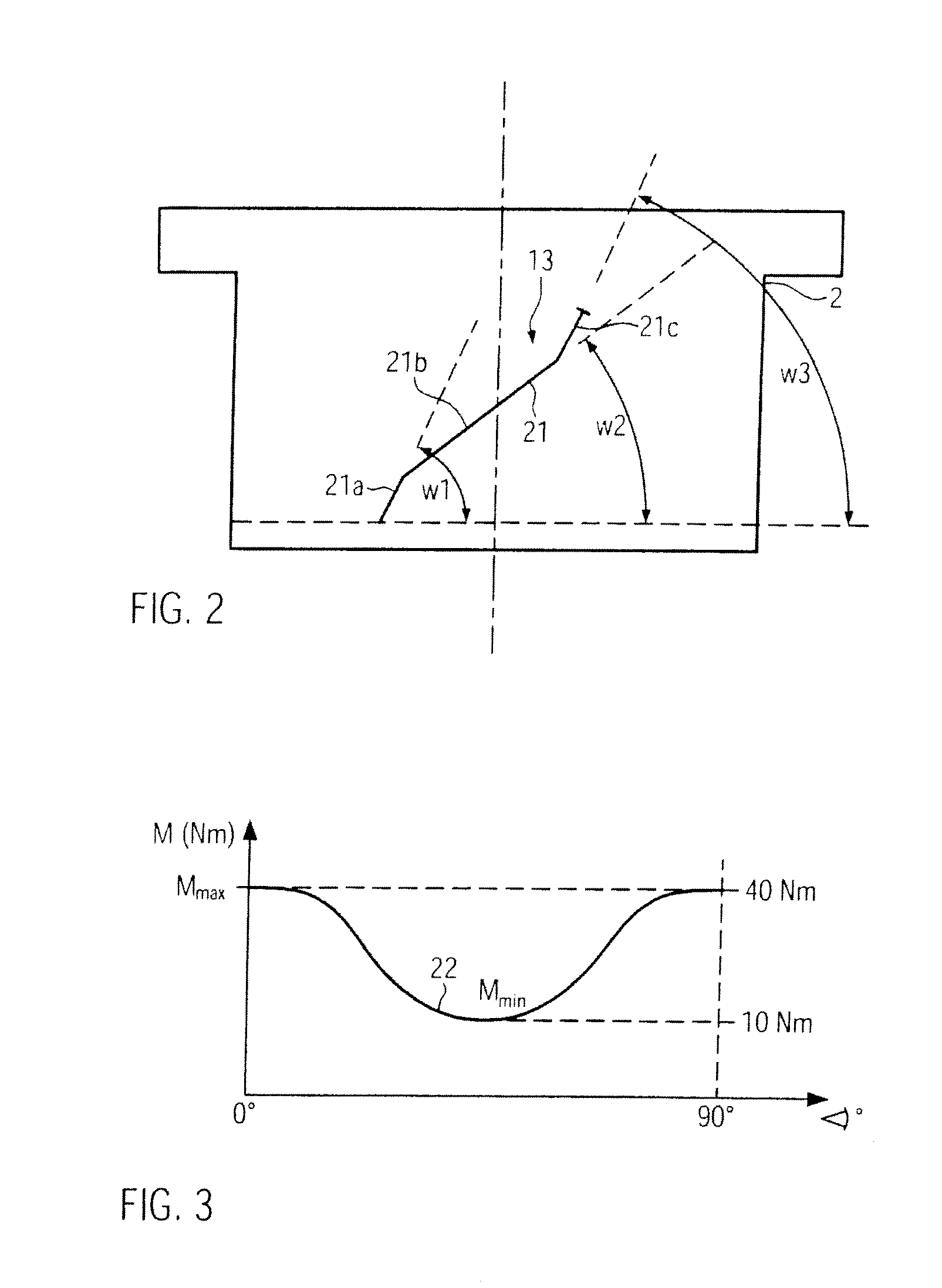
stroke end positions of the piston, the respective reaction torque is particularly stably introduced into the housing, the values and characteristics of the torques which then must be transmitted from the actuator to the function element, e.g. the closing element of a disk valve, can be very precisely predetermined and adjusted to the switching behavior of the disk valve, for example such that the preferably
plateau-like maxima of these torques are at the stroke end positions of the piston.
It is advantageous for the maximal free effective bending length of the one guide rod in a respective piston end position in the housing to correspond to between approximately half to two thirds of the piston's outer
diameter and / or approximately twice the overlap of the free ends of the two guide rods. This relatively short free effective bending length reduces the bending loads of this guide rod to a moderate degree, which is anyway supported by the other guide rod which can then very stably accept loads with a minimum free effective bending length.
Advantageously, each cover has one single mounting for a guide rod end. The guide rod is anchored with its end in the mounting by welding, screwing, shrinking, gluing or calking. Anchorage can be produced in an automated operating sequence, and thereby with high precision, so that readjustment of the anchored guide rods becomes dispensable.
Particularly advantageously, inexpensively and optimally in view of the quality of the anchorage, the guide rod is anchored with its end in the mounting of the cover by
friction welding, preferably automated
friction welding. The
friction welding operation results in a nearly monolithic anchorage and permits to implement exact positioning and alignment of the guide rod in the cover during friction welding, so that readjustment of the guide rod can be eliminated.
With respect to easy manufacturability, it can be advantageous to use as guide rods circular cylindrical
solid material rods, and to design the guides as blind holes in the piston. This should, however, not exclude to use also hollow profiles or tubes as guide rods, and to place the latter onto pins provided at the covers and anchor them e.g. by friction welding.

