Fastening mechanism of a fuel cell stack

A fuel cell stack and fixing mechanism technology, which is applied to fuel cell grouping, fuel cells, and fuel cell components, etc., can solve problems such as the complex structure of fuel cell stacks.

Inactive Publication Date: 2005-05-11
HYUNDAI MOTOR CO LTD
View PDF1 Cites 5 Cited by
  • Summary
  • Abstract
  • Description
  • Claims
  • Application Information

AI Technical Summary

Problems solved by technology

However, in this case, the separator should be redesigned relative to the conventional separator, and the fixing rods inserted into the separator lead to a more complicated structure of the fuel cell stack

Method used


Image

  • Fastening mechanism of a fuel cell stack
  • Fastening mechanism of a fuel cell stack
  • Fastening mechanism of a fuel cell stack

Examples


Embodiment Construction

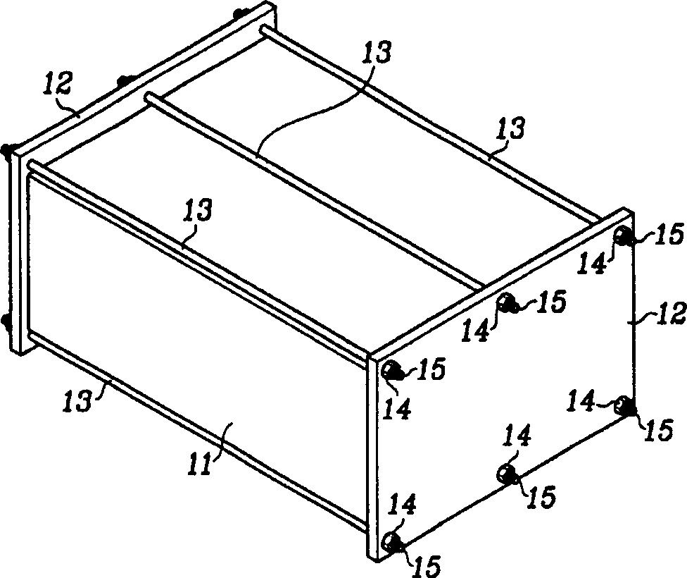
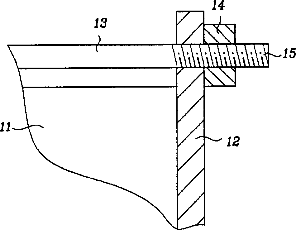
[0046] Embodiments of the present invention will be described in detail below with reference to the accompanying drawings. image 3 The fixing mechanism of the fuel cell stack according to the first embodiment of the present invention is shown.

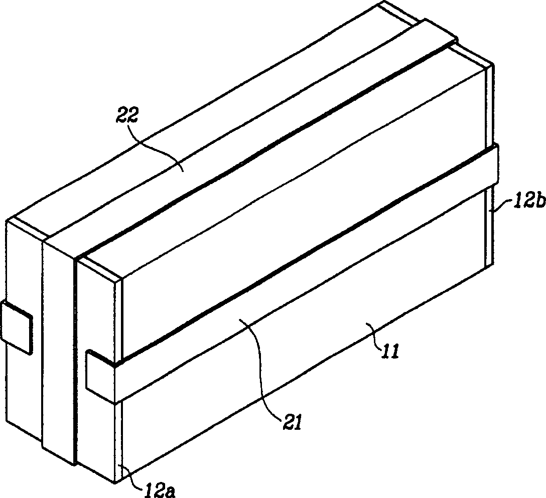
[0047] Such as image 3 As shown, MEAs and separators are stacked alternately to form a fuel cell stack 11, and end plates 12a and 12b are installed at both ends of the fuel cell stack 11, respectively.

[0048]The fuel cell according to the embodiment of the present invention includes a first fixing band 21 and a second fixing band 22 designed in a U shape.

[0049] The first fixing band 21 extends on two sides of the fuel cell stack 11 parallel to each other, and the second fixing band extends on a side parallel to each other, which is different from the side on which the first fixing band is placed.

[0050] Open ends of the first and second fixing straps 21 and 22 elastically press the different end plates 12a and 12b, and the f...


PUM


Abstract

A fuel cell fixing mechanism, comprising: a pair of end plates, which are respectively installed at both ends of the fuel cell stack to support the fuel cell stack; and a plurality of fixing belts extending in the stacking direction of the fuel cell stack, used for The end plates are pressed by a predetermined pressure. This securing mechanism creates uniform pressure on the separator and improves the sealing of the fuel cell stack.

Description

technical field [0001] The present invention generally relates to a fuel cell. More particularly, the present invention relates to a fixing mechanism for a fuel cell stack having a plurality of unit cells separated by a separator, wherein the surface pressure on the separator becomes more uniform by reducing the bending load acting on the separator . Background technique [0002] Typically, fuel cells use hydrogen H 2 and oxygen O 2 The reaction to generate electricity, and includes the membrane electrode assembly (MEA). [0003] The MEA includes a supply of hydrogen H 2 The anode and the cathode supplied with air are interposed between them to transport hydrogen ions H + electrolyte film. These MEAs and separators are stacked alternately to form a fuel cell stack. [0004] The sum of the output voltages of each unit cell constitutes the output voltage of the fuel cell stack. [0005] The performance of a fuel cell stack can be measured in terms of its output voltage...

Claims


Application Information

Patent Timeline
Patent Type & Authority Applications(China)
IPC IPC(8): H01M8/02H01M8/10H01M8/24H01M50/112
CPCH01M8/247H01M8/248Y02E60/50H01M8/24
Inventor 曹圭择金守焕黄云峰全志勋
Owner HYUNDAI MOTOR CO LTD
Why Eureka
Try Eureka