

Turbine convex sealing structure
A technology of turbines and blades, which is applied in the field of aero-engine turbine rotation and static sealing, which can solve the problems of gas intrusion, reduce engine life, fluid reduction, etc., and achieve the effect of reducing wind resistance, small wind resistance, and inhibiting gas intrusion
- Summary
- Abstract
- Description
- Claims
- Application Information
AI Technical Summary
Problems solved by technology
Method used
Image

Examples
Embodiment Construction
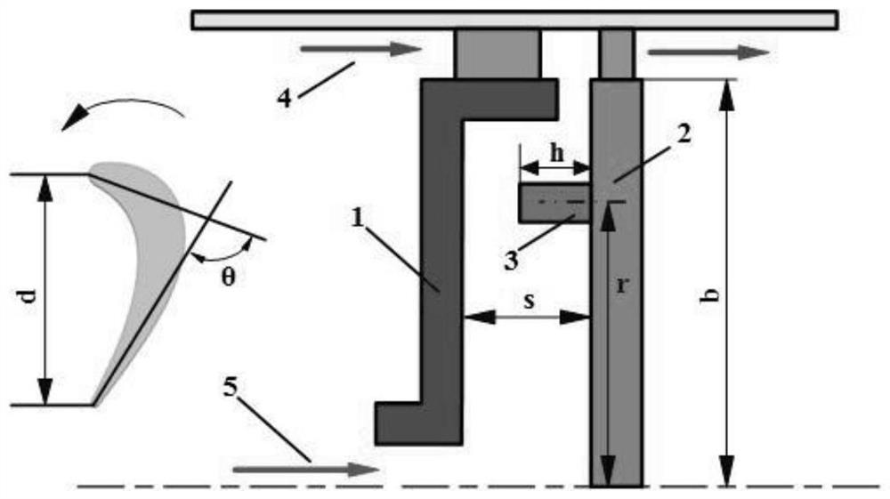
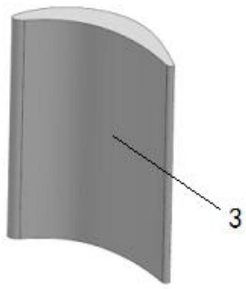
[0025] Such as figure 1 with 2 As shown, the sealing structure of the present invention is a blade-shaped protrusion 3, and the blade-shaped protrusion 3 is uniformly installed on the moving disk 2 of the rotating-stationary disk cavity with a simple radial sealing structure.
[0026] The radius of the moving disk is b, and the clearance ratio is s; the height h of the blade-shaped protrusion 3 is 1 / 3 to 2 / 3 of the rotational and static clearance s, and the chord length d is 1 / 3 to 4 / 3 of the rotational and static clearance s, The bending angle θ of the airfoil is 10°~70°, and the radial position r of the installation is 6 / 10~9 / 10 of the radius d of the moving disk.
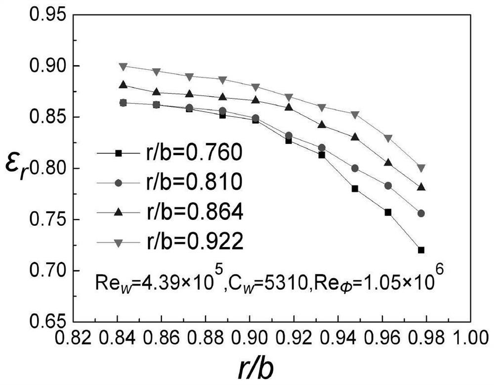
[0027] image 3 It is a comparison of the radial sealing efficiency of blade-shaped protrusions installed at different radial positions. It can be seen that with the same number of protrusions, the sealing efficiency increases as the installation radius increases. In addition, previous studies have shown that...
PUM
 Abstract
Description
Claims
Application Information