Novel rotor structure for hole-pattern seal

A technology of rotor structure and hole shape, applied in the direction of engine sealing, engine components, mechanical equipment, etc., can solve the effect of sealing and damping effect of hole shape seal, reduce the energy dissipation effect of hole shape seal, and the energy dissipation effect of round hole. Insufficient effect and other problems, to achieve the effect of reducing the straight-through effect, the new hole type sealing structure is simple, and promoting the separation of the boundary layer

Active Publication Date: 2015-12-23
SHENYANG AEROSPACE UNIVERSITY
View PDF4 Cites 0 Cited by
  • Summary
  • Abstract
  • Description
  • Claims
  • Application Information

AI Technical Summary

Problems solved by technology

Therefore, the smooth rotor leads to insufficient energy dissipation of the round hole, and the vortex formed in the hole is weak, which greatly reduces the energy dissipation of the hole seal and directly affects the sealing and damping effect of the hole seal.

Method used


Image

  • Novel rotor structure for hole-pattern seal
  • Novel rotor structure for hole-pattern seal
  • Novel rotor structure for hole-pattern seal

Examples


Embodiment Construction

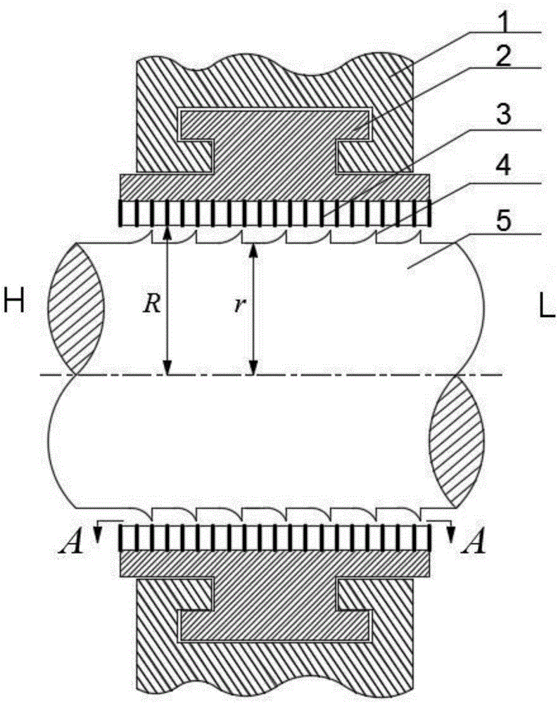
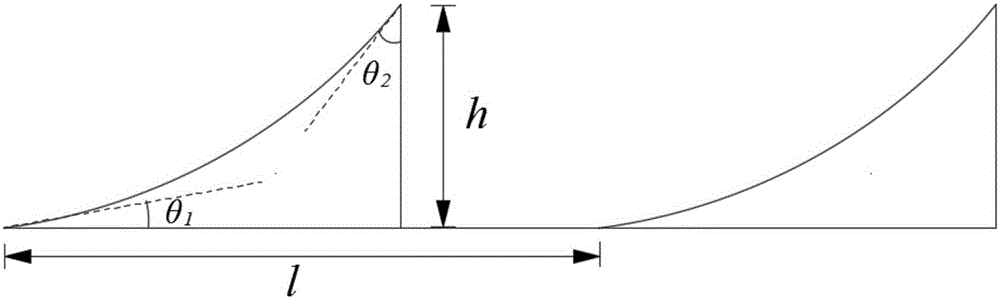
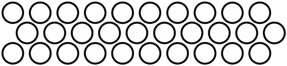
[0017] Such as Figure 1-Figure 3 Shown: a new type of hole-shaped sealed rotor structure, including a sealing sleeve 1, a sealing body 2, a hole-shaped belt 3, a circumferential concave arc wedge-shaped boss 4 and a rotor 5. The sealing body 2 is installed on the sealing sleeve 1, and the sealing body 2 is provided with a hole-shaped belt 3 in the circumferential direction, and the hole-shaped belt 3 is composed of several round holes. The sealing sleeve 1, the sealing body 2 and the perforated belt 3 all belong to the stator parts. The rotor 5 is in the annular cavity formed by the perforated belt 3 . The rotor 5 is provided with multiple sets of circumferential concave arc wedge-shaped bosses 4 on its circumferential surface in the axial direction, and the angle θ between the arc surface of the circumferential concave arc wedge-shaped bosses 4 and the rotor surface 1 =15°, the angle θ with the vertical surface of the boss 2 =30°, the radial height h of the circumferentia...


PUM


Abstract

The invention discloses a novel rotor structure for hole-pattern seal. The novel rotor structure comprises a sealing sleeve, a sealing body, hole-pattern strips, a plurality of sets of annular concave arc wedge-shaped bosses and a rotor. The sealing body is installed on the sealing sleeve. The hole-pattern strips are arranged on the sealing body in the circumferential direction, and each hole-pattern strip is composed of a plurality of round holes. The rotor is located in an annular cavity formed by the hole-pattern strips. The annular concave arc wedge-shaped bosses are arranged on the circumferential surface of the rotor in the radial direction. The included angle theta 1 between the arc surface of each annular concave arc wedge-shaped boss and the surface of the rotor ranges from 5 degrees to 45 degrees. The included angle theta 2 between the arc surface of each annular concave arc wedge-shaped boss and the vertical surface of the boss ranges from 5 degrees to 45 degrees. The radial height h of each arc surface of each annular concave arc wedge-shaped boss is 0.2-0.6 time a sealing diameter gap (R-r). The radial interval 1 between every two adjacent arc surface of each annular concave arc wedge-shaped bosses is 0.5-3 times the edge distances between each pair of hole patterns. According to the novel rotor structure for hole-pattern seal, separation of a boundary layer of jet fluid in the hole-pattern sealing gap can be promoted so that the energy dissipation function of the round hole can be brought into full play. Meanwhile, the flow resistance of the jet fluid in the sealing gap is increased through the wedge-shaped boss structures, and the pass-through effect causing sealing leak is reduced.

Description

technical field [0001] The invention relates to a dynamic sealing structure in a rotating machine, in particular to a novel hole-type sealing rotor structure. Background technique [0002] Hole seals are key components of rotating machinery such as aero-engines, steam turbines, and compressors. Compared with the traditional labyrinth seal, the perforated seal not only has better sealing characteristics, but also has better rotor dynamics characteristics. The hole type seal allows application under the condition of high pressure difference without increasing the size of the seal, and has high safety and reliability. Therefore, hole seals are widely used in rotating machinery in aerospace, electric power, petrochemical and other industries. [0003] The hole seal is mainly composed of a sealing sleeve, a sealing body, a hole belt and a rotor, and the hole belt is composed of several round holes. The flow field characteristics and sealing mechanism of the hole seal are as fo...

Claims


Application Information

Patent Timeline
Patent Type & Authority Applications(China)
IPC IPC(8): F16J15/16
Inventor 赵欢孙丹艾延廷王猛飞王良全蒋泽乾
Owner SHENYANG AEROSPACE UNIVERSITY
Why Eureka
Try Eureka