Check patentability & draft patents in minutes with Patsnap Eureka AI!

Method and device for separating gases and/or liquids

A kind of equipment and liquid technology, applied in the direction of separation method, chemical instrument and method, distillation separation, etc., can solve the problem of heat pump energy saving effect decline and so on

Inactive Publication Date: 2005-07-20
STICHTING ENERGIEONDERZOEK CENT NEDERLAND
View PDF0 Cites 1 Cited by
  • Summary
  • Abstract
  • Description
  • Claims
  • Application Information

AI Technical Summary

Problems solved by technology

[0003] The disadvantage of heat pumps is that they are most efficient when they are used to create relatively small temperature differences
With the existing heat pump, when it is used to establish a large temperature difference, it needs to use a relatively large-load compressor, and has to introduce a large amount of additional energy. As a result, the energy-saving effect of the heat pump will drop sharply

Method used


Image

  • Method and device for separating gases and/or liquids
  • Method and device for separating gases and/or liquids
  • Method and device for separating gases and/or liquids

Examples


Embodiment Construction

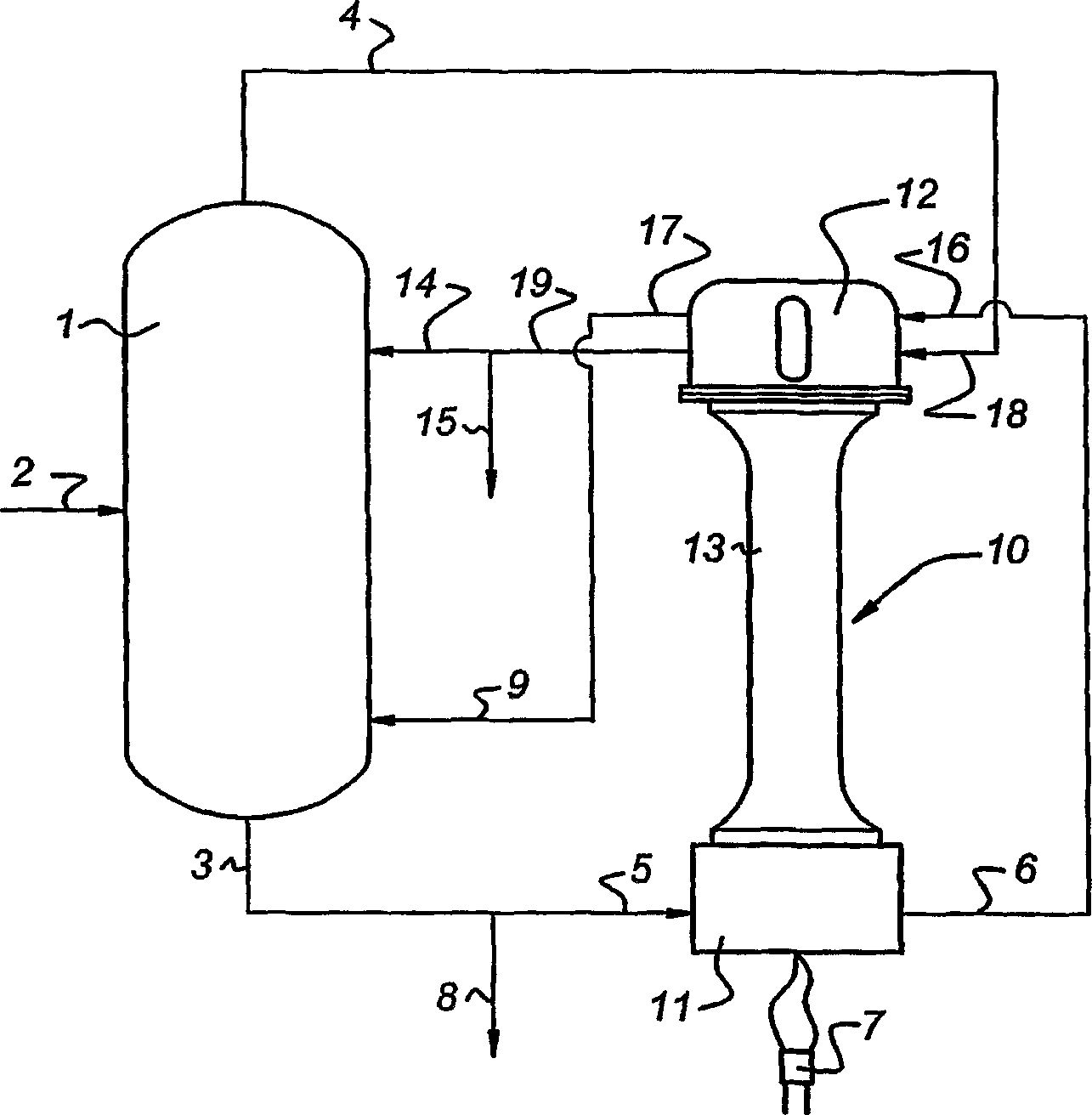
[0015] exist figure 1 In , the distillation column is indicated by reference numeral 1 . The distillation column is provided with an inlet 2 for the introduction of the product to be distilled. In addition, a bottom outlet 3 and a top outlet 4 are provided.

[0016] exist figure 1 In the example shown, the bottom outlet 3 is provided with a branch line 8 for withdrawing the bottom product, while some of the bottom product is fed into the low-temperature inlet 5 of the motor 11 of the thermoacoustic heat pump 10 . The thermoacoustic heat pump comprises a motor 11 and a pump 12 connected via a resonator 13 . The thermoacoustic heat pump can be any heat pump known in the art today. Sound waves are generated in the heat pump's motor. The sound waves can be generated in the motor by temperature differences. Said temperature difference is produced in the heat pump by the fact that the motor is provided with a burner 7 (hot part) and at a certain distance from it the cold flow ...


PUM


Abstract

Method and device for separating gases and / or liquids in a vertical column ( 1 ). The top product ( 4 ) of the column ( 1 ) is cooled and partly recycled. The bottom product ( 3 ) of the column ( 1 ) is heated and partly recycled. Cooling and heating take place with the aid of a thermoacoustic heat pump ( 10 ), which can be driven by external heating ( 2 ). A relatively large temperature difference between top product and bottom product can be overcome by this means.

Description

technical field [0001] A physicochemical process for implementation in one or more reactors, wherein heat is supplied to a first location in said reactor and heat is withdrawn from a second location in said reactor, said first The temperature of the location is higher than the temperature of the second location, and the transfer of heat from the second location to the first location is achieved by a heat pump. Background technique [0002] A method of the above-mentioned type is known in the prior art. In the case of distillation of a gas or gas mixture from a liquid, overhead and bottom products are produced in vertical separation columns. It is known in this respect that heat is extracted from the top product and transferred to the bottom product, and one of the two products is then partly recycled into the column. In this way, the desired temperature difference required for the separation is maintained in the most energy-efficient manner possible. Since the absolute te...

Claims


Application Information

Patent Timeline
IPC IPC(8): B01D3/14B01D3/00B01J19/10C07C27/28C07C29/80C07C31/12
CPCY02B30/52B01D3/007Y02B30/123B01J19/10
Inventor 西米恩·斯普尔斯特罗
Owner STICHTING ENERGIEONDERZOEK CENT NEDERLAND
Features
  • R&D
  • Intellectual Property
  • Life Sciences
  • Materials
  • Tech Scout
  • Unparalleled Data Quality
  • Higher Quality Content
  • 60% Fewer Hallucinations
Learn More