Control of air conditioning cooling or heating coil

A technology of control components and headers, applied in heating methods, lighting and heating equipment, space heating and ventilation, etc., can solve the problems of time-consuming water side balance of cold water systems and affecting system performance, etc., to ensure load performance and controllability sex, guaranteed low effect

Inactive Publication Date: 2005-09-07
IOTACS TECH
View PDF0 Cites 33 Cited by
  • Summary
  • Abstract
  • Description
  • Claims
  • Application Information

AI Technical Summary

Problems solved by technology

Achieving waterside balancing of chilled water systems is time cons

Method used


Image

  • Control of air conditioning cooling or heating coil
  • Control of air conditioning cooling or heating coil
  • Control of air conditioning cooling or heating coil

Examples


Embodiment Construction

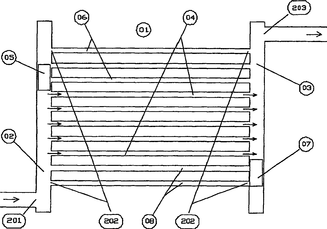
[0060] refer to figure 1 , The cold water coil 1 has a supply header 2, a return header 3 and an interconnection circuit 4 between the supply header and the return header. The plurality of interconnection circuits 4 are connected to the manifolds 2, 3 through corresponding plurality of connecting ports 202, the positions of the plurality of connecting ports 202 are different from each other and arranged in a line from top to bottom along the manifolds 2, 3. Row. The fluid flows into the supply header 2 through the supply port 201 at the bottom end of the header 2 and flows from the return header 3 through the return port 203 at the top end of the return header 3 . A sliding piston 5 is located in the supply manifold 2 and is equipped with a watertight seal to prevent the flow of water from the lower part to the upper part of this supply manifold 2 . In this figure, the piston 5 cuts off the water flow to the upper three circuits 6 where the coil surface temperature is the sa...


PUM


Abstract

A fluid heat exchange device, comprising a header and a plurality of interconnecting circuits between an supply port and a return port, the interconnecting circuits being connected to the header by a corresponding plurality of connection ports at different locations along the header wherein the header includes a blocking control element inside the header, the blocking control element being positionally adjustable along the header to selectively block fluid flow from the supply port through the connection ports of the plurality of interconnecting circuits, thereby selectively controlling those interconnecting circuits of the plurality of interconnecting circuits which are subjected to fluid flow therethrough in dependency on the position of the blocking control element.

Description

technical field [0001] The present invention relates to the improvement of the control of part load capacity of a fluid heat exchange device, especially a cooling (cooling) water cooling coil for air conditioning (treatment) equipment and fan coil units for comfort cooling and industrial applications . In the description below, the device is used for cooling applications, but the device can also be used for heating applications. Background technique [0002] When using a traditional throttle-controlled cooling coil at part load, its latent heat capacity drops much faster than its sensible heat capacity, which increases the relative humidity of the space and reduces comfort. Sensible heat sources upstream of the cooling coil other than in the conditioned space do not contribute effective sensible heat load from a latent heat removal standpoint. Coils need to be selected at full load with a high water side pressure drop to ensure turbulent flow in the circuit at part load. ...

Claims


Application Information

Patent Timeline
IPC IPC(8): F24F11/06F28D1/053F28F9/26F28F27/00F28F27/02
CPCF28F27/02F28F27/00F24F11/06F28D1/05316F24F11/83F24F11/85F24F11/84F28F9/26
Inventor G·S·维采瑙
Owner IOTACS TECH
Why Eureka
Try Eureka