Shielded connector

A connector and shielding technology, which is applied in the direction of connection, two-part connection device, and parts of the connection device, can solve the problems such as the loose engagement of the shell, and achieve the effect of increasing the degree of freedom

Inactive Publication Date: 2005-10-12
TYCO ELECTRONICS JAPAN GK
View PDF2 Cites 4 Cited by
  • Summary
  • Abstract
  • Description
  • Claims
  • Application Information

AI Technical Summary

Problems solved by technology

However, before the substrate is installed, the side walls of the upper case that overlap the lower c

Method used


Image

  • Shielded connector
  • Shielded connector
  • Shielded connector

Examples


Embodiment Construction

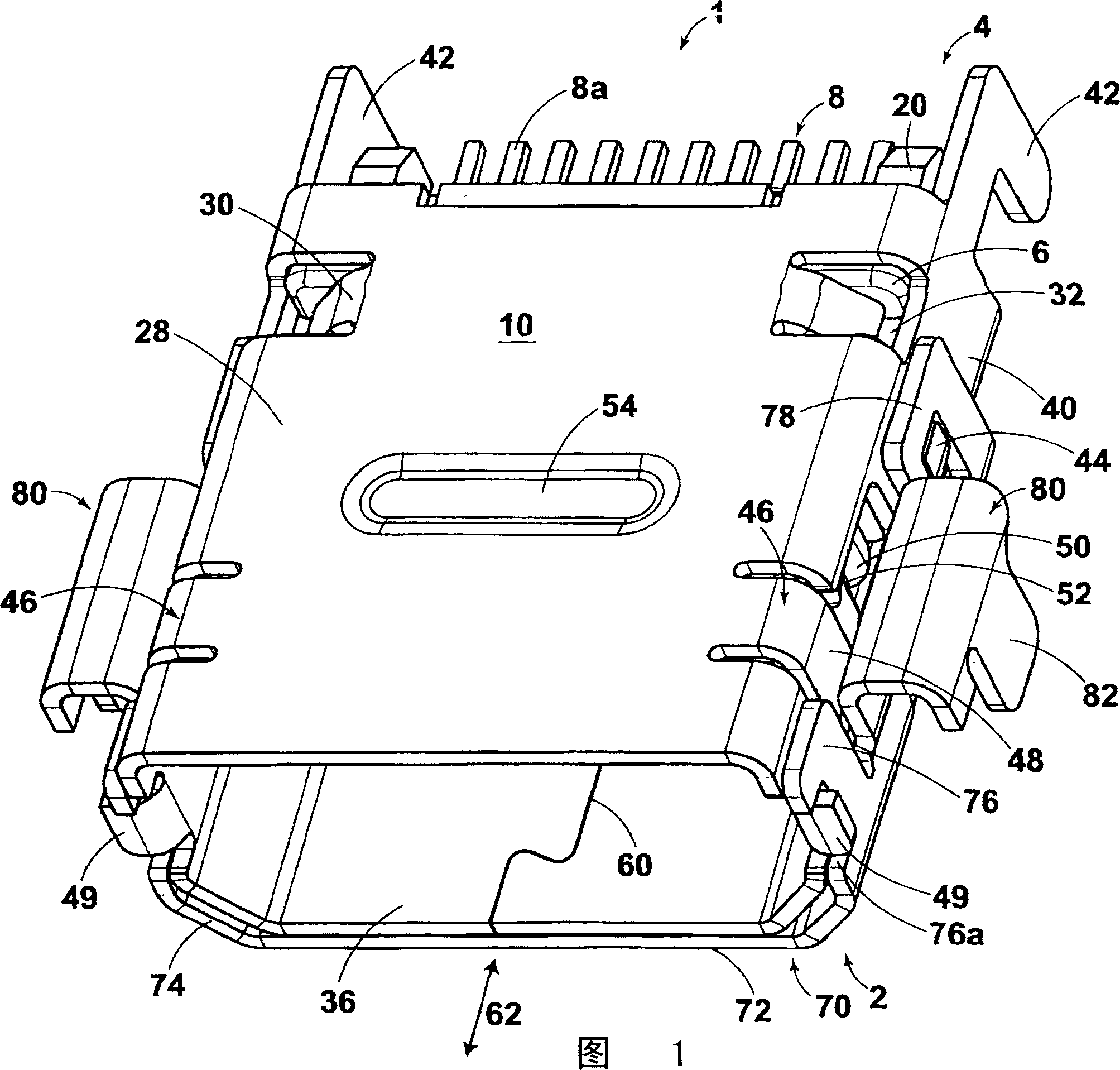
[0029] Hereinafter, preferred embodiments of the shielded connector (hereinafter simply referred to as a connector) of the present invention will be described in detail with reference to the drawings. FIG. 1 is a perspective view of a shielded connector (hereinafter simply referred to as a connector) 1 according to a first embodiment of the present invention viewed from a front portion 2 side. Hereinafter, description will be given with reference to FIG. 1 .

[0030] The connector 1 is composed of the following parts: an insulating cover (hereinafter simply referred to as a cover) 6, a plurality of contacts 8 held on the cover 6, and a shielding case (hereinafter simply referred to as a case) which is a shielding member arranged around the cover 6. body) 10 and the mounting member 70 arranged at the lower part of the casing 10 .

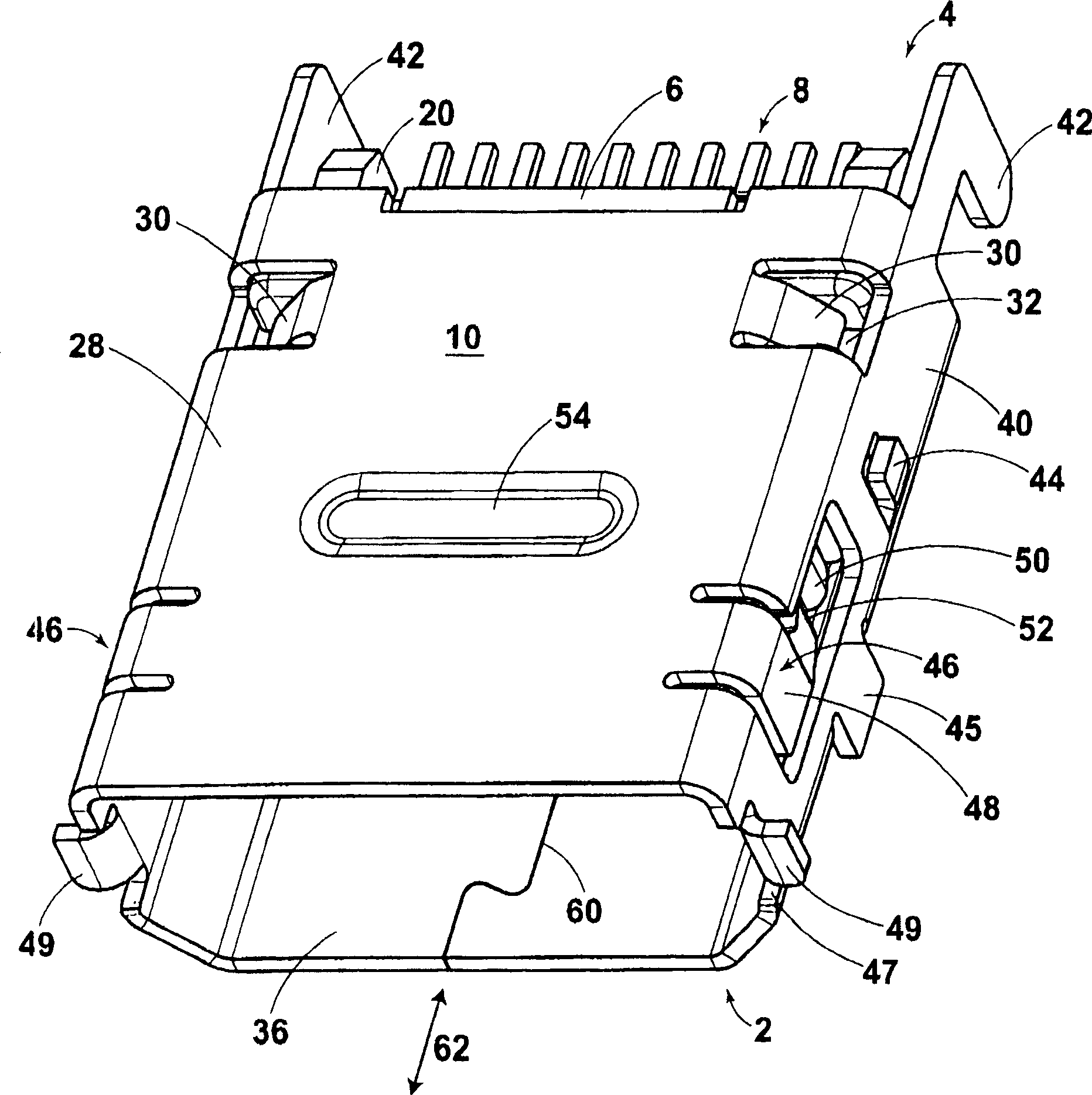
[0031] First, refer to figure 2 The case 10 will now be described. figure 2 is a perspective view of the casing 10 including the cover 6 . The...


PUM


Abstract

The present invention provided a shield type connector having a higher freedom in a position and a shape of a fitting leg for fitting it on a board, capable of keeping a unity by protecting joint partof a shield shell even before board mounting, capable of lowering the height from the board after mounting on the board. Of the shield type connector 1 provided with a contact 8, an insulation housing 6 housing the contact 8, and a metal shield shell 10 covering an outer periphery of the insulation housing 6 and having a joint on one face of the insulation housing 6, the shield shell 10 is equipped with a separate metal fitting member 70, which has a face covering the joint 60, and a fitting leg 82 for mounting the shield type connector 1 on the board 26 at positions corresponding to either side of the shield shell 10.

Description

technical field [0001] The present invention relates to a shielded connector used in electric / electronic devices such as mobile phones, and more particularly to a shielded connector mounted on a substrate arranged in a narrow space. Background technique [0002] As shielded connectors, various types of connectors are conventionally known. For example, there is a known connector in which a metal shield case is bent and arranged around a rectangular insulating cover (Patent Document 1). In this connector, a seam where the end edges of the shield case abut against each other is formed on the bottom surface of the shield case. Moreover, there are contact pieces on the bottom surface that are in contact with the shielding shell of the matched connector, and mounting feet that are cut out from the bottom surface and installed on the substrate are formed. [0003] In addition, there is a known connector in which a two-piece shield case is arranged around an insulating cover (Pate...

Claims


Application Information

Patent Timeline
IPC IPC(8): H01R13/648H01R24/00
CPCH01R12/722H01R13/6582H01R24/62
Inventor 井上昌士
Owner TYCO ELECTRONICS JAPAN GK
Why Eureka
Try Eureka